
Multi-rotors UAV (unmanned aerial vehicle)

A multi-rotor unmanned aerial vehicle and arm technology, which is applied in the directions of rotorcraft, unmanned aerial vehicle, fuselage, etc., can solve the problems of inconvenient disassembly and assembly, unstable arm, limited strength of pin shaft, etc. The effect of low cost, high structural strength and convenient manufacture

Pending Publication Date: 2017-06-13
泰华伟业科技有限责任公司
View PDF8 Cites 3 Cited by
  • Summary
  • Abstract
  • Description
  • Claims
  • Application Information

AI Technical Summary

Problems solved by technology

[0003] The motor is installed on the frame of the UAV through the arm. The arm is set radially outward relative to the fuselage. It is bulky and inconvenient to transport. At the same time, the arm structure is easy to collide during transportation, which affects the normal use of the UAV.
[0004] At present, the folding structure of the drone arm is mostly fixed by bolts, which is inconvenient to disassemble, or fixed by buckles or pins.
Due to structural limitations, there will be a gap between the arm and the frame after deployment, or the strength of the pin shaft is limited, especially for some drones with a large load, the pin shaft deforms after a period of use to create a gap
When the motor is running at high speed, high-frequency vibration is generated, which makes the arm unstable and affects the service life of the drone

Method used


Image

  • Multi-rotors UAV (unmanned aerial vehicle)
  • Multi-rotors UAV (unmanned aerial vehicle)
  • Multi-rotors UAV (unmanned aerial vehicle)

Examples


Embodiment Construction

[0024] One embodiment of the present invention will be further described below in conjunction with the accompanying drawings.

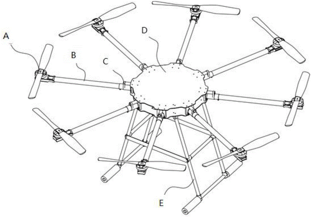
[0025] Such as figure 1 As shown, the multi-rotor UAV of the present invention includes a center plate D, a plurality of arms B evenly distributed around the center plate D, and the arms B are connected with the center plate D through a folding member C, and each arm A motor and a propeller A are fixed at the end; an undercarriage E is arranged under the center plate.

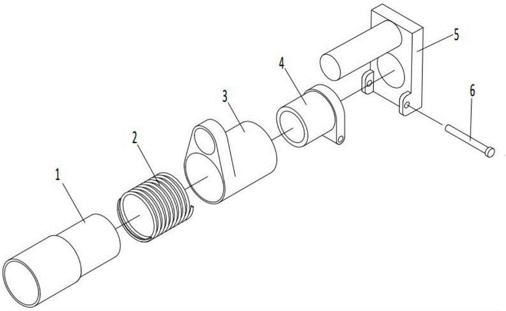
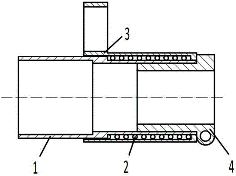
[0026] see Figure 2-7 , the arm folding part C of the multi-rotor UAV of the present invention is connected with the machine arm through the machine arm connecting part 1, including the machine arm connecting part 1, the spring 2, the sliding part 3, the limiting part 4, the fixing part 5 and the pin Axis 6, where,

[0027] The arm connector 1 is in the shape of a stepped shaft, the front part 11 is used to fix the machine arm through the locking structure 111, the outer diameter o...


PUM


Abstract

The invention relates to a multi-rotors UAV (unmanned aerial vehicle) arm folding mechanism, which is characterized in that the arm folding mechanism is connected with an arm through an arm adapting piece (1), and the mechanism comprises an arm adapting piece (1), a spring (2), a sliding part (3), a locating part (4), a fixed part (5) and a pin shaft (6), wherein the arm adapting piece (1) is in a stepped shaft shape, the arm is fixed by a front part (11) of the arm adapting piece through a locking mechanism (111), a rear part (12) is smaller than the front part (11) in the outer diameter, the rear part (12) is internally provided with an internal thread (121), and the spring (2) sleeves the rear part (12); the lower half (32) of the sliding part (3) is internally provided with a fixed hole, the sliding part (3) sleeves the spring (2) through a through-hole, a hole end (311) of the through-hole is cooperated with the rear part (12) of the arm adapting piece (1); the locating part (4) enables the axial direction of the sliding part (3) to be limited by a convex plate (42); the arm folding mechanism is fixed on a rack by the fixing part (5).

Description

technical field [0001] The invention relates to the field of multi-rotor UAVs, in particular to a foldable multi-rotor UAV. Background technique [0002] A multi-rotor UAV is a special unmanned helicopter with three or more rotor shafts. It is rotated by electric motors on each shaft, driving the rotors, thereby generating lift. By changing the relative rotational speed between different rotors, the size of the single-axis propulsion can be changed, thereby controlling the trajectory of the aircraft. [0003] The motor is installed on the frame of the UAV through the arm. The arm is radially arranged relative to the fuselage. It is bulky and inconvenient to transport. At the same time, the arm structure is easy to collide during transportation, which affects the normal use of the UAV. [0004] At present, the folding structure of the drone arm is mostly fixed by bolts, which is inconvenient to disassemble, or fixed by buckles or pins. Due to structural limitations, there ...

Claims


Application Information

Patent Timeline
IPC IPC(8): B64C1/30B64C27/08
CPCB64C1/30B64C27/08B64U10/10
Inventor 鲍奎宇田智博李希增甄鹏飞卢月竹边磊冯炳佐李朝喆李韬
Owner 泰华伟业科技有限责任公司
Learn More