Dynamic compactor and control method thereof

A technology of dynamic tamping machine and controller, applied in soil protection, construction, infrastructure engineering, etc., can solve problems such as uneven force on each part of the equipment, reduced power of the lifting device of the main roll, and inability to walk with load, etc., to achieve Improve assembly adjustment efficiency, improve work efficiency, and reduce labor costs

Inactive Publication Date: 2017-06-13
HANGZHOU HANGZHONG CONSTR MACHINERY
View PDF12 Cites 6 Cited by
  • Summary
  • Abstract
  • Description
  • Claims
  • Application Information

AI Technical Summary

Problems solved by technology

The existing main winch control system responds slowly, is inflexible, cannot travel with load, and has poor safety
In the existing main winch system with double disc brakes, one of the disc brakes is installed inside. Once it is damaged, it will be very troublesome to repair. The structure and function are single, and there is no point brake function.
Most of the existing slewing device hydraulic control systems use the main pump as an auxiliary belt slewing gear pump. For this slewing control system, because the core working device of the hydraulic compactor is the main roll lifting device, it works by the main pump. The rotary gear pump will consume part of the power in this way, whic...

Method used


Image

  • Dynamic compactor and control method thereof
  • Dynamic compactor and control method thereof
  • Dynamic compactor and control method thereof

Examples


Embodiment Construction

[0051] The application will be further described in detail below with reference to the accompanying drawings and embodiments. The following embodiments are an explanation of the application and the application is not limited to the following embodiments.

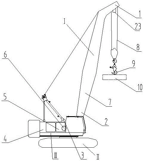
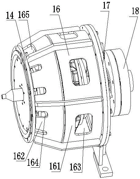
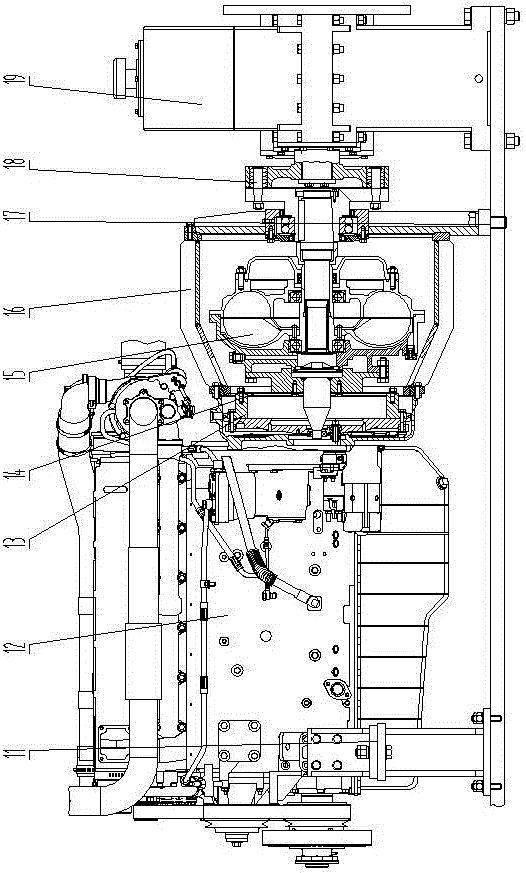
[0052] See Figure 1~Figure 16 The main structure of the embodiment of this application is the prior art, with working part I, walking part II, and operating platform III. The operating platform III is set on the walking part II, and the working part I is installed on the dynamic compactor (operating platform III or walking part Ⅱ) Above, working part I refers to the mechanical, electrical and hydraulic parts used to control, execute, display, and alarm the main operation and status of the dynamic compaction machine. The main improvements include: working part I includes the main winch 3 and its drive The main winch driving mechanism is provided with an engine 12, a coupler device, and a reduction box assembly 19, which is conne...


PUM


Abstract

The invention relates to a dynamic compactor which is provided with a working component, a walking component and an operating platform. The operating platform is arranged on the walking component, the working component is installed on the dynamic compactor and comprises a main winch and a driving mechanism thereof, the main winch driving mechanism is provided with an engine, a coupler device and a speed reduction box assembly. The speed reduction box assembly is connected with the main winch. The dynamic compactor is characterized in that the engine and the coupler device are fixed to be a whole and form an engine coupler assembly, and the engine coupler assembly and the speed reduction box assembly are coaxially installed. The invention further comprises a method for controlling the dynamic compactor. The dynamic compactor is simple in structure and convenient to use, construction data of the dynamic compactor can be automatically detected, and working efficiency and safety are improved.

Description

Technical field [0001] The application relates to a dynamic compaction machine and a control method thereof, which are mainly applied to a mechanical-hydraulic integrated dynamic compaction machine. Background technique [0002] The flexible coupling between the existing dynamic compaction machine engine and the reduction box has a set of elastic pin couplings at the input and output ends. The engine, coupler, and reduction box assembly are respectively installed and fixed on the dynamic compaction machine on the platform. When assembling, adjust the height and position of the front and rear support of the coupler, reducer, and engine to achieve the coaxiality of the three and to meet the installation of the two sets of elastic pin couplings before and after the coupler. It is difficult to adjust, the error of coaxiality is large, the radial jump of the coupling is large when the engine is running at high speed, the noise is large, the main parts are easy to wear, and the servic...

Claims


Application Information

Patent Timeline
IPC IPC(8): E02D3/046
CPCE02D3/046
Inventor 章伟达韩高青雷治龙东文黄峰包奇陆振峰胡艳华杨庆香王文俊莫建杰樊菁敏
Owner HANGZHOU HANGZHONG CONSTR MACHINERY
Why Eureka
Try Eureka