Hydraulic circulating power generation system

A power generation system and hydraulic cycle technology, which is applied to hydropower, engine components, machines/engines, etc., can solve the problems of long construction period, high cost, limited natural conditions, etc., and achieve the effect of convenient electricity consumption and simple structure

Inactive Publication Date: 2017-06-13
杨红炜
View PDF0 Cites 3 Cited by
  • Summary
  • Abstract
  • Description
  • Claims
  • Application Information

AI Technical Summary

Problems solved by technology

At present, hydropower generation has become one of the important methods of power production. The existing hydropower generation mainly relies on damming the river (river) for hydropower generation, which has the disadvantages of being limited by natural conditions, costing a lot, and having a long construction period.

Method used


Image

  • Hydraulic circulating power generation system
  • Hydraulic circulating power generation system
  • Hydraulic circulating power generation system

Examples


Embodiment Construction

[0032] The principles and features of the present invention are described below in conjunction with the accompanying drawings, and the examples given are only used to explain the present invention, and are not intended to limit the scope of the present invention.

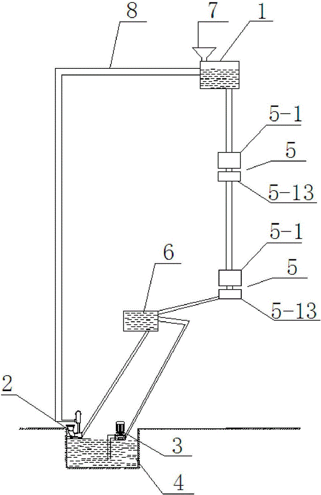
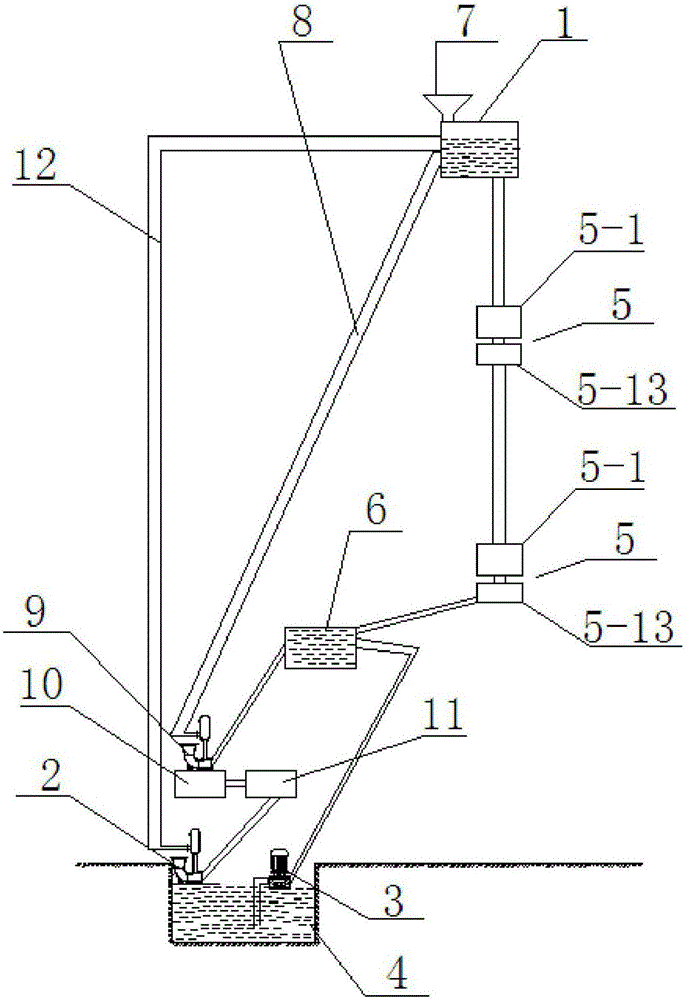
[0033] Such as figure 1 As shown, the present invention includes a circulating water tank 1, a water hammer pump 2, an electric water pump 3 and a water storage tank 4. The bottom of the circulating water tank 1 is connected with a plurality of hydroelectric power generation devices 5 through pipelines from top to bottom in sequence, and the plurality of The bottom of the hydroelectric generating device 5 located at the lowest horizontal position among the hydroelectric generating devices 5 is connected to the water storage tank 6 located at a low horizontal position through a pipeline, and the input end 2-7 of the water hammer pump is connected to the water storage tank 6 through a pipeline. The water storage tank ...


PUM


Abstract

The invention relates to a hydraulic circulating power generation system, and in particular relates to a hydraulic circulating power generation system. Multiple hydraulic power generation devices are connected below a circulating water tank from top to bottom by virtue of pipelines sequentially, the bottom of one hydraulic power generation device, arranged at the lowest horizontal position, of multiple hydraulic power generation devices is connected with a water storage tank at a lower horizontal position by virtue of a pipeline, the input end of a water hammer pump is communicated with the water storage tank by virtue of the pipeline, the output end of the water hammer pump is communicated with the upper part of the circulating water tank by virtue of a first water loading pipeline, the horizontal height of the water hammer pump is lower than the horizontal height of the water storage tank, the input end of an electric water pump is communicated with the water storage tank, and the output end of the electric water pump is communicated with the upper part of the water storage tank and / or the upper part of the hydraulic power generation device at the lowest end of the horizontal height through a pipeline. The hydraulic circulating power generation system provided by the invention has the beneficial effects that the structure is simple, the potential energy of water can be converted into electric energy, and convenience is provided for household electricity consumption.

Description

technical field [0001] The invention relates to a hydropower generation system, in particular to a hydropower cycle power generation system. Background technique [0002] With the progress of society and the understanding of the limitations of petrochemical energy applications, people pay more and more attention to various equipment that directly converts natural forces into power. At present, hydropower generation has become one of the important methods of power production. The existing hydropower generation mainly relies on damming the river (river) for hydropower generation, which has the disadvantages of being limited by natural conditions, costing a lot, and having a long construction period. . Contents of the invention [0003] The technical problem to be solved by the present invention is to provide a water cycle power generation system with simple structure and effective power generation. [0004] The technical scheme of the present invention to solve the above-m...

Claims


Application Information

Patent Timeline
Patent Type & Authority Applications(China)
IPC IPC(8): F03B13/06F04F7/02
CPCF03B13/06F04F7/02Y02B10/50Y02E10/20Y02E60/16
Inventor 杨红炜
Owner 杨红炜
Why Eureka
Try Eureka