Automatic synchronous gear shifting system and electric automobile

A technology for automatic synchronization and shifting of motors, applied in control/regulation systems, transmission control, instruments, etc., can solve problems such as reduced reliability of shifting, long synchronization time, and large shifting force

Inactive Publication Date: 2017-06-13
HEBEI UNIV OF TECH
View PDF7 Cites 15 Cited by
  • Summary
  • Abstract
  • Description
  • Claims
  • Application Information

AI Technical Summary

Problems solved by technology

However, if only a single forward gear transmission is installed, it is difficult to meet the driving performance requirements of users and car manufacturers. Therefore, the transmission of electric vehicles is developing in the direction of two gears and multi-speed. Multi-speed transmissions can improve vehicle acceleration performance and make the drive motor work normally. In the high-efficiency range, the power consumption of the motor is reduced, and the cruising range and economy are improved
However, the existing electric vehicle shifting system generally uses a synchronizing ring to realize the synchronization process between the gear sleeve and the engaging teeth. During the shifting process, there are problems such as shifting impact, large shifting force and long synchronization time, and the existing automatic shifting system Generally, there is a device to prevent the gear sleeve from being out of gear, which increases the complexity of the gear shifting system and reduces the reliability of gear shifting.

Method used


Image

  • Automatic synchronous gear shifting system and electric automobile
  • Automatic synchronous gear shifting system and electric automobile
  • Automatic synchronous gear shifting system and electric automobile

Examples


Embodiment Construction

[0027] The technical solutions of the present invention are further described below with reference to the accompanying drawings and through specific embodiments.

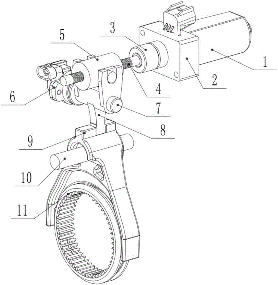
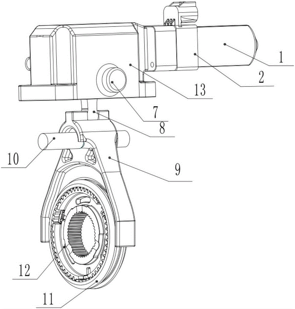
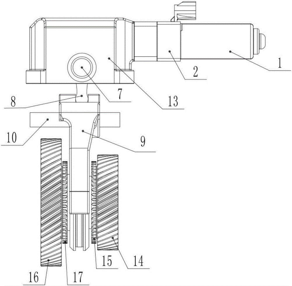
[0028] like Figures 1 to 3 As shown, the automatic synchronous shifting system includes a power mechanism, a deceleration mechanism, a shifting fork mechanism and a shifting mechanism. The power mechanism includes a shifting motor 1, a controller 2 and an engaging sleeve 3. The shifting motor 1 is fixedly installed on the The outer and inner parts of the housing 13 are connected by flanges with simple structure, reliable performance, low cost and suitable for mass production. The controller 2 is fixedly installed on the output end of the shift motor 1, the end of the controller 2 away from the shift motor 1 is fixedly connected with the joint sleeve 3, the reduction mechanism includes a lead screw 4 and a nut sleeve 5, and one end of the lead screw passes through the joint sleeve 3 Drivenly connected with the outp...


PUM


Abstract

The invention discloses an automatic synchronous shifting system and an electric vehicle, belonging to the technical field of electric vehicles. The automatic shifting system provided by the present invention includes a power mechanism, a deceleration mechanism, a fork mechanism and a shifting mechanism. The deceleration mechanism of the present invention uses a lead screw and a nut sleeve to form a lead screw and nut pair. Compared with the self-locking pin or positioning pin that prevents off-gear in the existing automatic shifting system, the use of the lead screw and nut pair can not only achieve self-locking and The purpose of deceleration also simplifies the structure of the entire shifting system. The present invention also provides an electric vehicle using the above-mentioned automatic shifting system, the automatic synchronous shifting system for electric vehicles not only has a self-locking function, but also has low cost and reliable performance, and also saves the synchronous ring structure, thereby improving The shifting speed is reduced and the shifting shock is reduced.

Description

technical field [0001] The invention relates to the technical field of electric vehicles, in particular to an automatic shifting system and an electric vehicle applying the automatic synchronous shifting system. Background technique [0002] Electric vehicles refer to vehicles that are powered by on-board power and drive wheels with motors, which are in line with road traffic and safety. Compared with traditional vehicles, electric vehicles have the advantages of less environmental pollution, low noise, simple structure and convenient maintenance. . [0003] The electric vehicle adopts the electronic control system to control the voltage or current of the motor installed on the drive axle of the electric vehicle, so as to realize the control of the driving torque and rotation direction of the motor. Since the motor of the electronic control system can realize the motor reversal, the pure electric vehicle does not need to be equipped with a reverse gear device compared with...

Claims


Application Information

Patent Timeline
Patent Type & Authority Applications(China)
IPC IPC(8): F16H61/32F16H63/32
CPCF16H61/32F16H63/32F16H2063/322
Inventor 李光鑫陈勇曹展董远李卓强
Owner HEBEI UNIV OF TECH
Why Eureka
Try Eureka