Rear-arch-free flow smoothening device for garbage incinerator

A waste incinerator and incinerator technology, which is applied in the field of downstream equipment without back arches, can solve the problems of insufficient consideration of radiation and convective heat transfer, poor flame fullness, lack of experience, etc., and achieve simple and easy technical means and reduce combustion The effect of temperature and prolonged exercise time

Pending Publication Date: 2017-06-13
GRANTOP GRP CO LTD
View PDF5 Cites 3 Cited by
  • Summary
  • Abstract
  • Description
  • Claims
  • Application Information

AI Technical Summary

Problems solved by technology

In addition, in terms of furnace design, due to the lack of understanding of the characteristics of China's low calorific value, high moisture, and high ash waste, the lack of experience in the design of the volumetric heat load of the furnace and the heat load of the grate area, the radiation of the front and rear arches of the furnace Insufficient consideration of convective heat transfer makes the flame fullness in the furnace poor, and the overall temperature in the furnace is not high, especially for wet garbage with low calorific value, so more coal or oil has to be added to assist combustion

Method used


Image

  • Rear-arch-free flow smoothening device for garbage incinerator
  • Rear-arch-free flow smoothening device for garbage incinerator
  • Rear-arch-free flow smoothening device for garbage incinerator

Examples


Embodiment 1

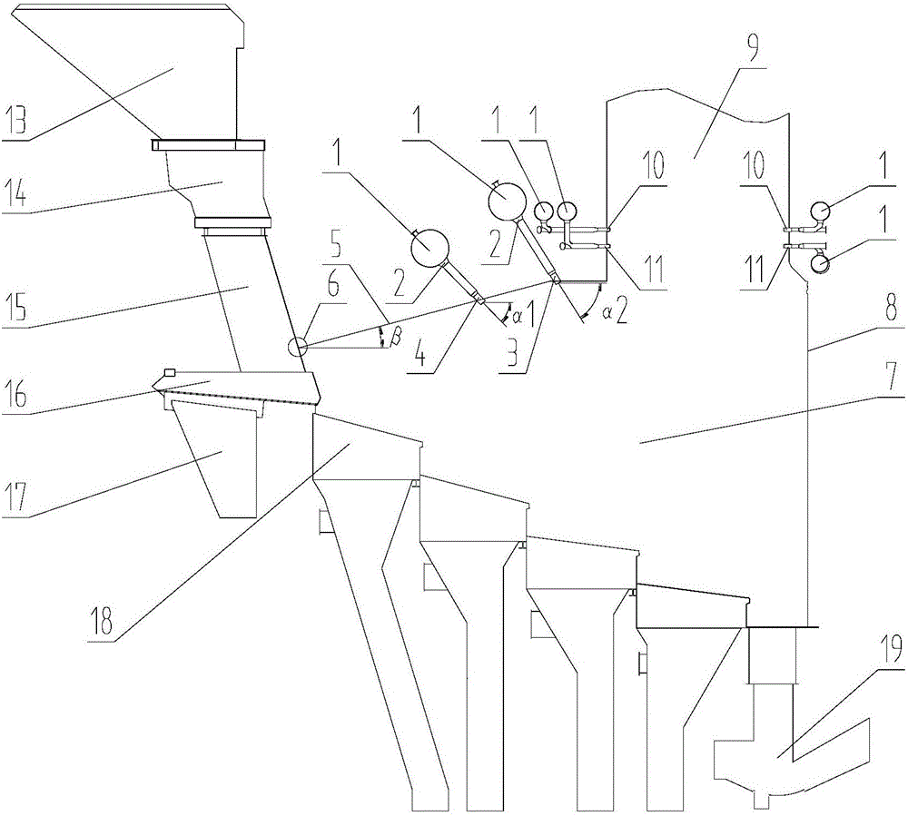
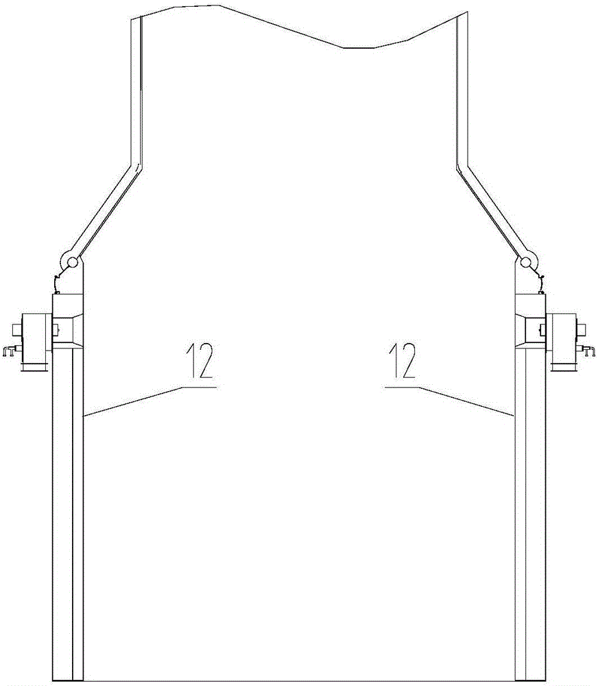
[0026] Such as figure 1 Shown, in the existing basic incinerator side walls 12, garbage feed hopper 13, feed baffle 14, water-cooled chute 15, pusher 16, ash hopper 17, fire grate 18, slag machine 19 foundations On, the present invention has flue 9 especially, and there is furnace 7 below flue 9, and one side of furnace 7 is rear wall 8, and there are front supply 5 and front supply lower header 6 in furnace 7, and described front supply 9 The upper water wall fin is provided with at least one upper layer secondary air nozzle 3 and the throat upper layer secondary air nozzle 10, and at least one lower layer secondary air nozzle 4, and the throat lower layer secondary air nozzle 11 each layer two The air inlets of the secondary air nozzles are respectively connected with the secondary air pipes (1), and secondary air doors (2) are arranged at the joints between the air nozzles of each layer described above and the secondary air pipes (1).

Embodiment 2

[0028] Same as Example 1, except that the vertical distance between the horizontal section of the upper secondary air nozzle 3 and the lower header 6 of the front arch is 1.6m to 1.8m, and the horizontal section of the secondary air nozzle 4 of the lower layer is located at 6 The vertical distance is 1.0m ~ 1.3m.

Embodiment 3

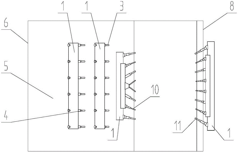
[0030] Same as Embodiment 1, except that there are two layers of secondary air nozzles on the upper and lower layers of the front arch, each layer has 6 nozzles, which are respectively arranged at intervals on the front arch, and there are 12 secondary air nozzles in total in the two layers.


PUM


Abstract

The invention relates to a rear-arch-free flow smoothening device for a garbage incinerator, and belongs to devices special for environment-friendly enterprises. The device comprises a flue (9), a hearth (7) is arranged below the flue (9), a rear wall (8) is arranged on one side of the hearth (7), a front arch (5) and a front arch lower collection box (6) are arranged in the hearth (7), water-cooling wall fins on the upper portion of the front arch (9) are provided with at least one upper layer secondary air nozzle (3), throat upper layer secondary air nozzles, at least one lower layer secondary air nozzles (4) and throat lower layer secondary air nozzles 11, an air inlet of each secondary air nozzle on each layer is communicated with one secondary air pipe (1), and a secondary air door (2) is arranged on the joint of each secondary air nozzle on each layer and the corresponding secondary air pipe (1). The device achieves the aims of treatment of low-heat-value high-water-content high-ash content garbage in China and power generation.

Description

technical field [0001] The invention relates to a kind of incineration equipment which burns garbage and utilizes waste heat to generate electricity, especially a back-bow downstream equipment which can optimize combustion and simplify furnace structure for large-scale garbage incineration. Background technique [0002] With the development of the national economy and urban construction, more and more garbage is produced, and land resources are becoming more and more tense. According to the forecast of the Ministry of Environmental Protection, the amount of garbage will reach 179 million tons and 210 million tons in 2015 and 2020, making waste incineration power generation technology a new trend and new hotspot in many cities to solve the problem of garbage. The waste incineration method can reduce the volume of waste by 90%, and reduce the volume by 70%-80%, greatly reducing the occupied land area, which meets the requirements of reduction; the waste heat of waste incinerat...

Claims


Application Information

Patent Timeline
Patent Type & Authority Applications(China)
IPC IPC(8): F23G5/44F23L9/02
CPCF23G5/44F23L9/02
Inventor 刘先荣罗翠红张焕亨张钦华吴荫津余笑枫冯建华朱燕云黄东涛
Owner GRANTOP GRP CO LTD
Why Eureka
Try Eureka