
Detection method of linear grating ruler

A technology of linear grating and detection method, which is applied to measurement devices, optical devices, instruments, etc., can solve the problems of relying on manual point-finding measurement results and large influence, and achieve the effect of automatic detection, elimination of influence, and convenient detection.

Active Publication Date: 2017-06-13
HEILONGJIANG PROVINCIAL INST OF MEASUREMENT & VERIFICATION
View PDF4 Cites 8 Cited by
  • Summary
  • Abstract
  • Description
  • Claims
  • Application Information

AI Technical Summary

Problems solved by technology

[0005] The present invention solves the problem that the current linear grating ruler detection method can only rely on manual point finding and the problem that human factors have a great influence on the measurement results

Method used


Image

  • Detection method of linear grating ruler
  • Detection method of linear grating ruler
  • Detection method of linear grating ruler

Examples


specific Embodiment approach 1

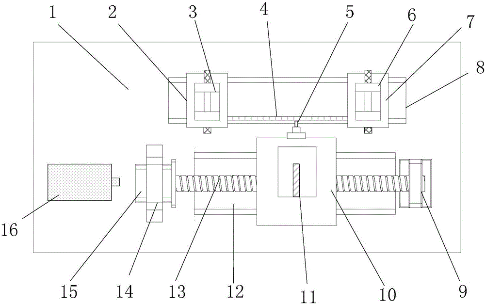
[0043] The detection method of the linear grating ruler is realized based on the detection device of the one-dimensional linear grating ruler;

[0044] like figure 1 As shown, the detection device of the one-dimensional linear grating ruler includes a base 1, a displacement reference mechanism, a displacement transmission mechanism and a three-optical axis laser interferometer 16;

[0045] The displacement reference mechanism includes a first clamping slider 2, a first clamping mechanism 3, a second clamping slider 7, a second clamping mechanism 6 and a slider guide seat 8;

[0046] The displacement transmission mechanism includes a motor 15, a ball screw 13, a ball guide seat 12, a ball slider 10, a grating reading head 5, and a bearing seat 9;

[0047] The slider guide seat 8 and the ball guide seat 12 are arranged on the base 1; axis parallel;

[0048] The first clamping slider 2 and the second clamping slider 7 are both arranged on the slider guide seat 8 and can move a...

specific Embodiment approach 2

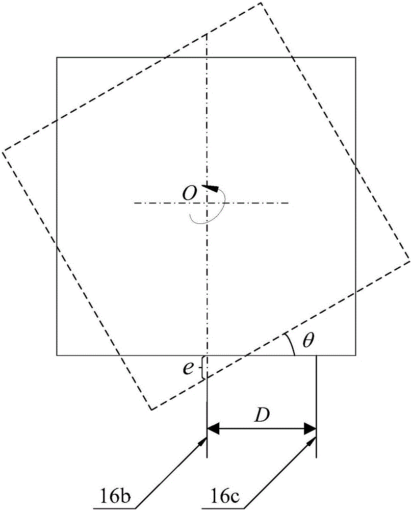
[0071] Specific implementation mode 2: Combining figure 2 and image 3 Describe this embodiment,

[0072] In step 5 of this embodiment, for the i-th measurement point, the displacement values ​​sαi' and sγi' measured by the three-axis laser interferometer are used to compensate sβi' to obtain s i ' The process includes the following steps:

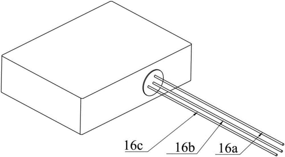
[0073] For the i-th measurement point, the deflection angle is obtained from the distance D between the second beam 16b and the third beam 16c

[0074] Then, according to the distance D and the deflection angle θ, the displacement deviation e on the second beam 16b caused by the deflection is calculated, and then through the formula s i '=sβi'-e compensate sβi' to get s i '.

[0075] Other steps and parameters are the same as in the first embodiment.

specific Embodiment approach 3

[0077] In the fifth step of this embodiment, e=Dsinθ.

[0078] Other steps and parameters are the same as in the second embodiment.


PUM


Abstract

The invention discloses a detection method of a linear grating ruler, relates to a detection technology of a precision measuring instrument, and mainly relates to the detection method of the linear grating ruler. The method comprises the following steps of selecting N measuring points at equal intervals within a detecting stroke of a ball sliding block; when the ball sliding block moves to a selected measuring point, synchronously acquiring displacement measurement values salphai', sbetai' and sgammai' measured by three beams of laser of a three-optical axis laser interferometer, and optical grating distance data si on the detected linear grating ruler; performing compensation on the salphai', sbetai' and sgammai' to obtain si'; and performing linear fitting on the compensated data si' of each measuring point to obtain a function, modifying the compensated data si' of each measuring point to obtain yi, and taking the ratio of max|yi-si| to total range A as a detection standard of the detected linear grating ruler, thus realizing detection on the linear grating ruler. The method is used for detecting the linear grating ruler.

Description

technical field [0001] The invention relates to a detection technology of a precision measuring instrument, and mainly relates to a detection method of a linear grating ruler. Background technique [0002] The grating line displacement sensor and the linear moving guide mechanism constitute the grating line displacement measuring device, such as: grating universal tool microscope, grating length measuring machine, length ratio meter, three-coordinate measuring machine, gear measuring center, wheel set press machine, CNC machining center, CNC machine tools, grinding machines, milling machines, automatic unloaders, sheet metal pressing and welding machines, robots and other automation technology devices. Grating line displacement measuring device is a precision measuring instrument, which is widely used in my country's equipment manufacturing industry, and occupies an important position in precision machining, industrial production, metrology verification and other industries....

Claims


Application Information

Patent Timeline
Patent Type & Authority Applications(China)
IPC IPC(8): G01B11/02
CPCG01B11/02
Inventor 张海波韩正阳李浩周彤刘文滨陈涛
Owner HEILONGJIANG PROVINCIAL INST OF MEASUREMENT & VERIFICATION
Learn More