
Network-based soil detection system

A soil detection and network technology, applied in the field of network-based soil detection system, can solve the problems of urgent soil detection, difficult soil self-purification, easy to be restricted by regions, etc. The effect of improving safety

Inactive Publication Date: 2017-06-13
安聪聪
View PDF0 Cites 5 Cited by
  • Summary
  • Abstract
  • Description
  • Claims
  • Application Information

AI Technical Summary

Problems solved by technology

[0002] With the development of society, the development of chemistry has been promoted, and chemical fertilizers have emerged. Because chemical fertilizers are low-cost, chemical fertilizers are basically used in planting and animal husbandry now, but long-term use of chemical fertilizers is likely to cause soil pollution. And the degree of pollution, the soil itself is difficult to purify itself, and these polluted soils are washed into the river by rainwater, which is likely to cause eutrophication of the river's water quality, so soil testing is urgent, and technicians can formulate different treatments based on the soil conditions after testing Programs to Improve Soil Pollution
[0003] Soil pollution at the present stage is not only polluted by chemical fertilizers, more soil will be doped with some metals, which will disturb the crops in the soil by heavy metals, and the soil that has been used for a long time will be affected by changes in humidity and pH. The function of the soil is changed to a large extent, thereby affecting the growth of crops. The data collected by traditional soil testing equipment is cumbersome and requires a lot of manual input. Therefore, it is necessary to detect the soil in time and transmit the data to the management office. It is very cumbersome to analyze, and the soil conditions in different regions are different, so it is easy to be restricted by region

Method used


Image

  • Network-based soil detection system
  • Network-based soil detection system

Examples


Embodiment Construction

[0029] The technical solutions in the embodiments of the present invention will be clearly and completely described below in conjunction with the accompanying drawings in the embodiments of the present invention. Obviously, the described embodiments are only a part of the embodiments of the present invention, rather than all the embodiments. Based on the embodiments of the present invention, all other embodiments obtained by those of ordinary skill in the art without creative work shall fall within the protection scope of the present invention.

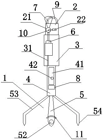
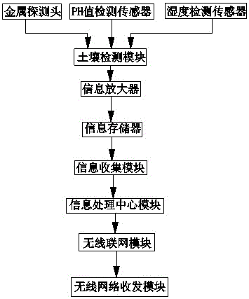
[0030] See figure 1 As shown, the embodiment of the present invention provides a network-based soil detection system, including a soil detection device 1. The soil detection device 1 is provided with a wireless network transceiver module 2, an information processing center module 3, and information collection from top to bottom. Module 4, soil detection module 5; the wireless network transceiver module 2 is provided with a wireless networ...


PUM


Abstract

The invention discloses a network-based soil detection system, which comprises a soil detector. The soil detector is provided with a wireless network transceiver module, an information processing center module, an information collection module and a soil detection module from top to bottom. A wireless networking module is arranged inside the wireless network transceiver module. One side of the wireless networking module is equipped with central monitoring equipment which is used for monitoring network transmission to raise safety and accuracy of data information. An information two-way transmission line is arranged inside the information processing center module and is used for receiving and transmitting acquired information data. An information memory is disposed inside the information collection module, and an encryption unit is arranged inside the information memory. A soil metal content detector is arranged inside the soil detection module. The system of the invention has a simple structure, is convenient and fast, has advantages of fast information data transmission, high safety performance, accurate detection data and network transmission, and can get rid of geographical limitations.

Description

Technical field [0001] The invention relates to the technical field of soil detection, in particular to a network-based soil detection system. Background technique [0002] With the development of society, the development of chemistry was promoted, and chemical fertilizers were born from this. Because chemical fertilizers are low-cost, chemical fertilizers are basically used in planting and animal husbandry. However, long-term use of chemical fertilizers can easily lead to soil pollution. And the degree of pollution, the soil itself is difficult to self-purify, and these contaminated soil enters the river after the rainwater washes, it is easy to cause the eutrophication of the river water quality, so soil testing is urgent, technicians can make different treatments based on the soil conditions after testing Program to improve soil pollution. [0003] The current soil pollution is not only the pollution of chemical fertilizers, more soil will be doped with some metals, which will ...

Claims


Application Information

Patent Timeline
Patent Type & Authority Applications(China)
IPC IPC(8): G01N33/24
CPCG01N33/24G01N33/245
Inventor 安聪聪
Owner 安聪聪
Learn More