
Distribution automation system ground fault location method based on traveling wave measure and transient zero-module reactive power directions

A technology for distribution automation and ground faults, which is applied to fault locations, fault detection according to conductor types, and electrical measurement. It can solve the difficulties of ground faults in non-effectively grounded power grids at neutral points, and the accuracy of sample data is restricted and restrictive. question

Active Publication Date: 2017-06-13
国网山东省电力公司聊城供电公司 +1
View PDF9 Cites 2 Cited by
  • Summary
  • Abstract
  • Description
  • Claims
  • Application Information

AI Technical Summary

Problems solved by technology

However, this patent requires a large amount of sample data as a basis, and is restricted by the accuracy of the sample data, which is too restrictive
[0007] To sum up, it is very difficult to accurately monitor the ground fault due to the influence of many factors on the non-effectively grounded power grid at the neutral point.

Method used


Image

  • Distribution automation system ground fault location method based on traveling wave measure and transient zero-module reactive power directions
  • Distribution automation system ground fault location method based on traveling wave measure and transient zero-module reactive power directions
  • Distribution automation system ground fault location method based on traveling wave measure and transient zero-module reactive power directions

Examples


Embodiment

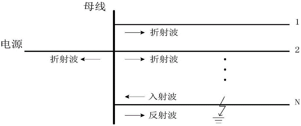
[0114] The distribution automation system ground fault location method based on traveling wave measurement and transient zero-mode reactive power direction, using the software MATLAB to establish a model for simulation verification, the distribution automation system is a 110kV / 10kV substation, with 6 feeders, K open When the neutral point is not grounded, when K is closed, it is a resonant grounded system. Such as Figure 7 As shown, the calculation step size of the simulation software is: 1μs, that is, 1×10 -6 s. The fault conditions are as follows: ① The initial phase angle of the fault is simulated in three situations of 30°, 60° and 90° respectively. ② Transition resistance, respectively take 10Ω, 100Ω and 500Ω for simulation. ③ The location of the fault point is 4km, 5km, 6km away from the busbar and the busbar. Specific steps include:

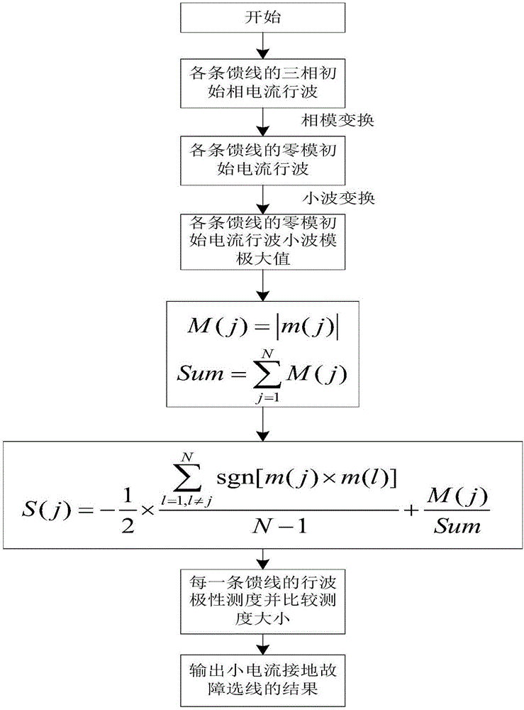
[0115] (1) Use the small current line selection method of traveling wave measurement to point out the possibility of ground faults...


PUM


Abstract

The invention relates to a distribution automation system ground fault location method based on a traveling wave measure and transient zero-module reactive power directions. The method comprises the steps that firstly which feeder a ground fault is located on is determined by means of the small current line selection method of the traveling wave measure; secondly, based on the transient zero-module reactive power flow directions, a ground fault point is localized on a fault feeder, wherein on the feeder where the ground fault is located, the transient zero-module reactive power flow directions of any two adjacent feeder terminal units (FTUs) are monitored, if the product of the transient zero-module reactive power flow directions of some two adjacent feeder terminal units (FTUs) is negative, it is explained that the ground fault is located between the two adjacent feeder terminal units (FTUs), and if the product of the transient zero-module reactive power flow directions of some two adjacent feeder terminal units (FTUs) is positive, it is explained that no ground fault exists between the two adjacent feeder terminal units (FTUs). By means of the method, the ground fault is accurately localized, and which two feeder terminal units (FTUs) the ground fault is located between is determined, and good sensitivity is achieved to a high-resistance ground fault.

Description

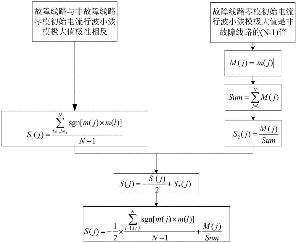
technical field [0001] The invention relates to a grounding fault location method for a distribution automation system based on traveling wave measurement and transient zero-mode reactive power direction, and belongs to the technical field of distribution automation system grounding fault location. Background technique [0002] The fault measure refers to a positive real number that can characterize the similarity between the characteristics of each feeder and the fault feeder under a certain criterion. Among multiple feeders of the same voltage level grid, if the fault measure of a certain feeder is the largest, it can indicate that the possibility of the feeder being a fault feeder is the greatest. The traveling wave measure refers to a positive real number that can characterize the similarity between the characteristics of each feeder and the fault feeder under the zero-mode initial current traveling wave polarity benchmark. Among the multiple feeders of the grid with th...

Claims


Application Information

Patent Timeline
IPC IPC(8): G01R31/08
CPCG01R31/086G01R31/088Y04S10/52
Inventor 闫光太李祯史吏刘德才王和先蔡军黄国强闫昊张庆海李豹张斌
Owner 国网山东省电力公司聊城供电公司
Learn More