
Asymmetric directional coupler

A directional coupler, asymmetric technology, applied in the field of optical communication, to achieve the effect of simplifying design, reducing process cost and improving coupling efficiency

Inactive Publication Date: 2017-06-13
UNIV OF ELECTRONICS SCI & TECH OF CHINA
View PDF5 Cites 15 Cited by
  • Summary
  • Abstract
  • Description
  • Claims
  • Application Information

AI Technical Summary

Problems solved by technology

[0004] The purpose of the present invention is to solve the problem that there is no better solution in the prior art to realize the conversion between odd mode and even mode, and proposes an asymmetric directional coupler

Method used


Image

  • Asymmetric directional coupler

Examples


Embodiment Construction

[0015] The embodiments of the present invention will be further described below in conjunction with the drawings.

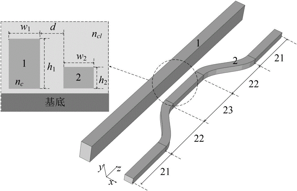
[0016] The present invention provides an asymmetric directional coupler, such as figure 1 As shown, a multi-mode waveguide 1 and a single-mode waveguide 2 are included. The cross-sectional height of the multimode waveguide 1 is h 1 , The width is w 1 , The cross-sectional height of the single-mode waveguide 2 is h 2 , The width is w 2 , H in the embodiment of the present invention 1 ≠h 2 , W 1 ≠w 2 .

[0017] The single-mode waveguide 2 includes input and output regions 21 at both ends, a coupling region 23 in the middle part, and an s-bend region 22 for connecting the input and output regions 21 and the coupling region 23. Among them, the two sections of input and output areas 21 have the same structure and are arranged symmetrically. In practical applications, the end connected to the input waveguide is the input area, and the end connected to the output waveguide...


PUM


Abstract

The invention discloses an asymmetric directional coupler. The asymmetric directional coupler comprises a multi-mode waveguide (1) and a single-mode waveguide (2), wherein the height and width of the cross section of the multi-mode waveguide (1) are different from those of the single-mode waveguide (2). A traditional directional coupler can be used for easily implementing coupling of two odd-modes or two even-modes in an optical fiber, but cannot be used for converting odd-modes and even-modes in the horizontal direction since the coupling coefficient determined by electric field distribution characteristics of the odd-modes and even-modes is zero. In the asymmetric directional coupler, widths and heights of two waveguides are not equal, so that the symmetricity of a device in the vertical direction is destroyed, conversion between odd-modes and even-modes in the optical fiber can be especially realized. The asymmetric directional coupler can be used as a mode converter, a mode multiplexer / demultiplexer, and can be applied to mode division multiplexing optical fiber communication systems.

Description

Technical field [0001] The invention belongs to the technical field of optical communication, and specifically relates to the design of an asymmetric directional coupler. Background technique [0002] The directional coupler (DC) is an important basic structure that constitutes an optical fiber communication system and an integrated optical waveguide circuit. A typical directional coupler is composed of two waveguides, and the energy is periodically coupled in two modes of the two waveguides, which can realize the functions of energy distribution, switching, wavelength division multiplexing, and polarization beam splitting. In recent years, mode-division multiplexing (MDM) technology has gradually emerged. Mode-division multiplexing has attracted attention as a key component. A typical mode multiplexer can be implemented based on the following structure: Multimode interference structure (Multimode interference), Y branch, microcircle, DC, etc. Compared with other structures, th...

Claims


Application Information

Patent Timeline
IPC IPC(8): G02B6/28
CPCG02B6/2804
Inventor 陈开鑫赵伟科
Owner UNIV OF ELECTRONICS SCI & TECH OF CHINA
Learn More