
Eureka
For R&D, Eureka makes reading and utilizing patents & technical documents easy.
Eureka AIR
Designed for self-driven R&D workflows. Generate viable solutions, solve complex R&D challenges, empower your innovation with AI.

Eureka Materials
Designed for material experts only. Revolutionize your material R&D, from search, analyze, to developing new materials.

TechResearch
Generate reliable direction feasibility study reports for your R&D in just a few steps.

TechSeek
Discover and master advanced knowledge NOW. Basics, ideas, possibilities, all at once.

TechMind
As an expert in R&D Theories, TechMind can generates customized viable solutions instantly.

TechRisk
Analyze your overall solution with one click, know your potential R&D risks in advance.

TechMonitor
Get weekly tech updates, stay abreast of the latest tech innovations and key insights.
Touch point determining method and device for infrared touch screen
A technology of infrared touch screen and determination method, which is applied in the direction of instruments, electrical digital data processing, and input/output process of data processing, etc., which can solve the problems of only identifying two points, slow scanning speed, and increased cost, so as to improve analysis and Calculation speed, reduced data volume, and fast acquisition speed
- Summary
- Abstract
- Description
- Claims
- Application Information
AI Technical Summary
Problems solved by technology
Method used
Image

Examples
Embodiment 1
[0085] According to an embodiment of the present invention, an embodiment of a method for determining a touch point on an infrared touch screen is provided. It should be noted that the steps shown in the flow chart of the accompanying drawings can be implemented in a computer system such as a set of computer-executable instructions and, although a logical order is shown in the flowcharts, in some cases the steps shown or described may be performed in an order different from that shown or described herein.
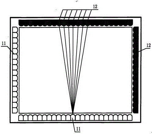
[0086] It should be noted that the method of the present invention is applied to an array of infrared emitting tubes and infrared receiving tubes arranged around the touch area, connecting the auxiliary circuits of the infrared emitting tubes and infrared receiving tubes, controlling the circuits and storing, In the infrared touch screen composed of a microcontroller system that calculates and transmits the detected data.
[0087] like figure 1 As shown, the infrared touch...
Embodiment 2
[0151] Such as Figure 9 As shown, the present invention also provides a device for determining a touch point on an infrared touch screen. The infrared touch screen composed of the auxiliary circuit and the microcontroller system that controls the circuit and stores, calculates and transmits the detected data also includes:
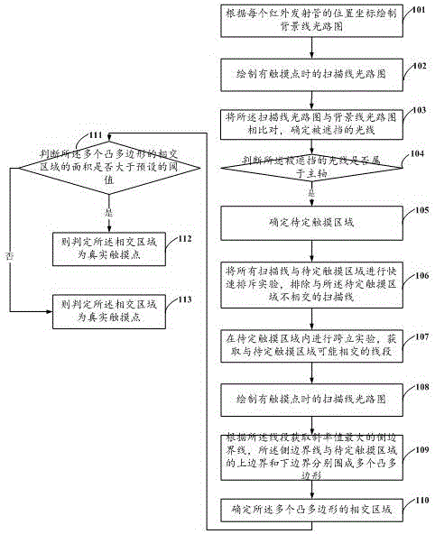
[0152] The first drawing module 10 is used to draw the background line light path diagram according to the position coordinates of each infrared emitting tube;
[0153] The second drawing module 20 is used to draw the light path diagram of the scanning line when there is a touch point;
[0154] The undetermined touch area determination module 30 is used to compare the light path diagram of the scanning line with the light path diagram of the background line to determine the blocked light; judge whether the blocked light belongs to the main axis; if so: the light to be blocked The horizontal axis intersects the vertical axis, and the undetermined touch a...
PUM
 Abstract
Description
Claims
Application Information
 - R&D Engineer
- R&D Manager
- IP Professional
- Industry Leading Data Capabilities
- Powerful AI technology
- Patent DNA Extraction
Browse by: Latest US Patents, China's latest patents, Technical Efficacy Thesaurus, Application Domain, Technology Topic, Popular Technical Reports.
© 2024 PatSnap. All rights reserved.Legal|Privacy policy|Modern Slavery Act Transparency Statement|Sitemap|About US| Contact US: help@patsnap.com