Vehicle drive device controller

A technology of driving device and control equipment, which is applied in the direction of transmission control, transmission, traction driven by engine, etc., can solve the problems of complex learning, difficulty in obtaining learning results accurately, etc., so as to improve fuel economy and inhibit conversion. Efficiency loss, size reduction effect

Inactive Publication Date: 2008-07-23
TOYOTA JIDOSHA KK
View PDF1 Cites 8 Cited by
  • Summary
  • Abstract
  • Description
  • Claims
  • Application Information

AI Technical Summary

Problems solved by technology

In this case, unlike the structure in which the transmission is independently provided with a learning control for learning the engagement pressure of the engagement device associated with shifting, it is likely that such learning is complicated
In other words, ...

Method used


Image

  • Vehicle drive device controller
  • Vehicle drive device controller
  • Vehicle drive device controller

Examples


Embodiment 1

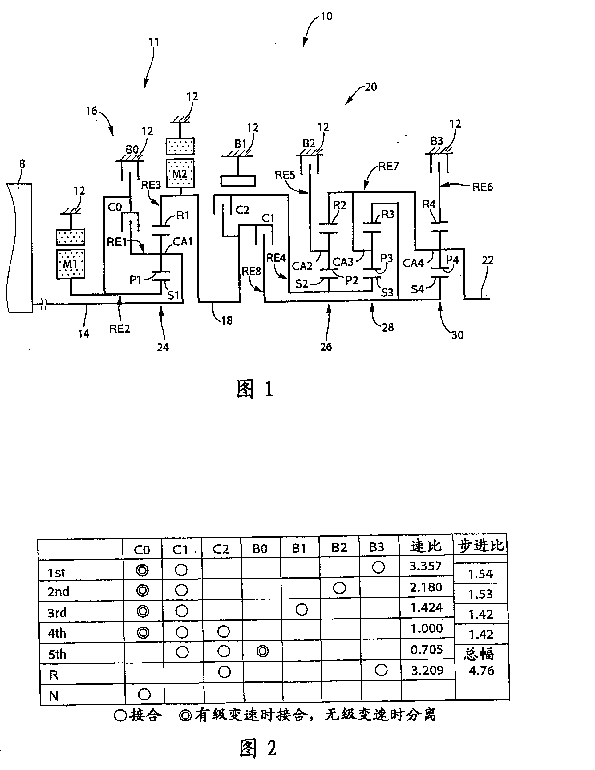
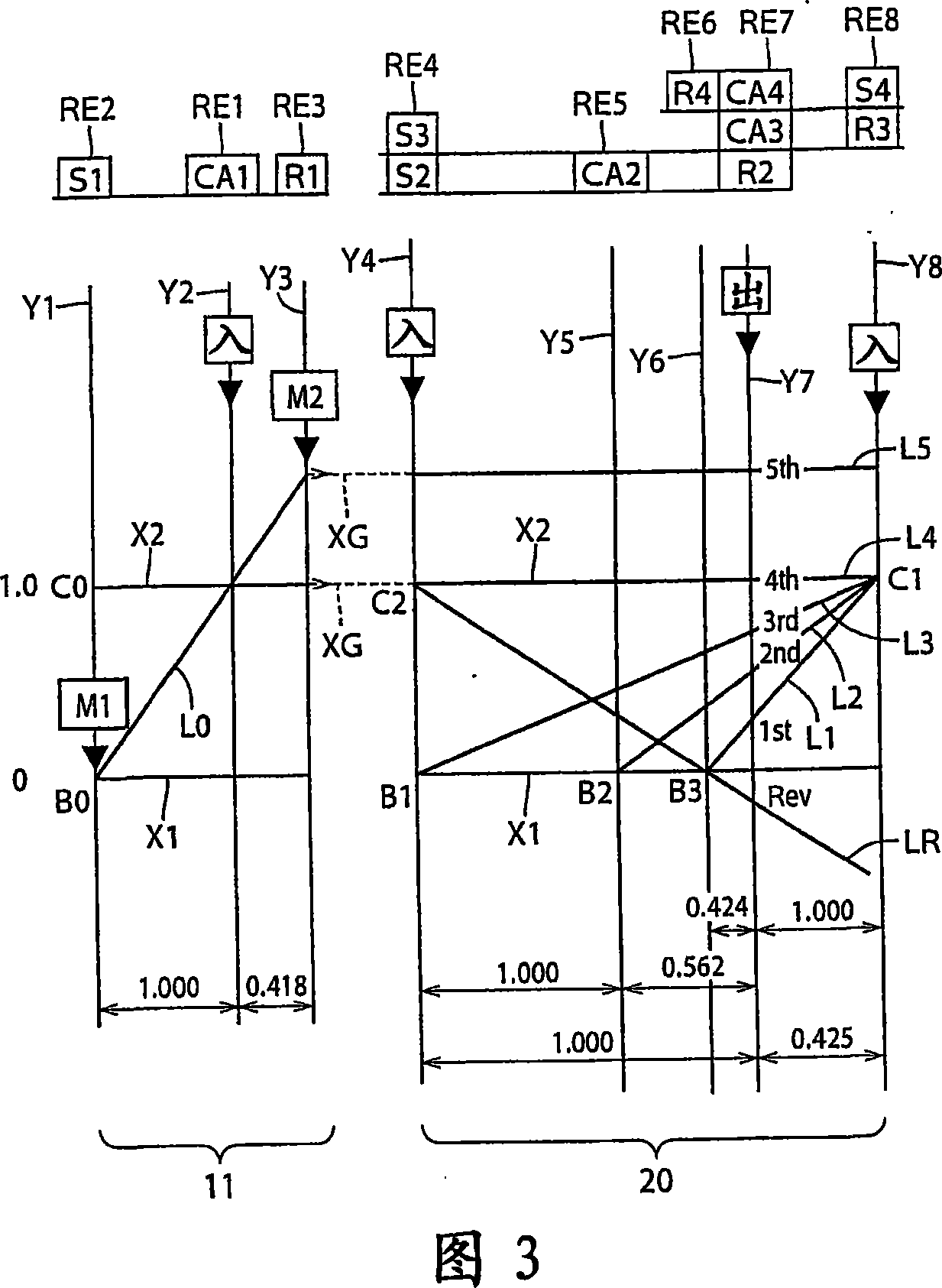
[0135] FIG. 1 is a skeleton diagram showing a speed change mechanism (ie, transmission mechanism) 10 constituting a part of a driving device for a hybrid vehicle according to an embodiment of the present invention. A transmission mechanism (ie, transmission mechanism) 10 includes an input shaft 14, a differential portion 11, an automatic transmission portion 20, and an output shaft 22, all of which are coaxially arranged in a transmission case 12 as a non-rotatable member fixed to a vehicle body. (hereinafter referred to as "housing 12"). An input shaft 14 as an input rotating member is fixed to the housing 12 . A differential portion 11 functioning as a continuously variable transmission portion is directly or indirectly connected to an input shaft 14 via an unillustrated pulsation absorbing damper (vibration damper). An automatic transmission portion 20 (ie, an automatic transmission portion functioning as a stepped transmission) is disposed between the differential mechani...

Embodiment 2

[0400] FIG. 20 is a skeleton diagram illustrating the structure of a transmission mechanism 70 according to another embodiment of the present invention. The actuation of FIG. 21 shows the relationship between the actuation combination of the shift stage of the transmission mechanism 70 and the hydraulic friction engagement device used therefor. The nomographic diagram of FIG. 22 illustrates the shifting operation of the shifting mechanism 70 .

[0401] Like the above-mentioned embodiment, the transmission mechanism 70 includes a differential portion 11 and an automatic shift portion 72, the differential portion 11 includes a first electric motor M1, a power distribution mechanism 16, and a second electric motor M2, and the automatic shift portion 72 communicates with the differential through the transmission member 18. Section 11 and output shaft 22 are connected in series and have three forward gears. The power distribution mechanism 16 includes a first planetary gear unit 2...

Embodiment 3

[0416] FIG. 23 shows an example of an interactive switch 44 (hereinafter referred to as "switch 44") as shift state manual selection means, which is mounted on a vehicle and manually operated by a vehicle driver. The switch 44 allows manual operation to selectively place the power distributing mechanism 16 into a differential state and a non-differential state (locked state), that is, the continuously variable state and the stepped state of the transmission mechanism 10 . Switch 44 allows the vehicle to travel in the shift state desired by the driver of the vehicle. The switch 44 has: a continuously variable speed change driving command button, on which "stepless" is displayed, indicating a continuously variable speed change driving mode; . When the driver of the vehicle presses one of these buttons, the transmission mechanism 10 is selectively placed in a continuously variable transmission state operable as an electronically controlled continuously variable transmission or a...


PUM


Abstract

In a vehicle drive device comprising a differential mechanism and a motor provided therein, size of the drive device can be reduced, fuel consumption is improved, or occurrence of speed change shock is suppressed. Since an exchange clutch C0 or an exchange brake B0 is provided, a speed change mechanism (10) is switched between a variable speed state and a stepped speed state so as to obtain a drive device having both advantages of fuel consumption improvement of a transmission having a speed change ratio electrically altered and high transmission efficiency of a gear type transmission for mechanically transmitting power. During speed change of an automatic speed change section (20), learning method of engaging pressure is altered by an engaging control amount control means (84) according to the fact whether a differential section (11) is in variable speed change state or not, and the rotational speed N18 of a transmission member is varied to satisfy both enhancement of feeling and suppression of speed change shock depending on the stepless speed change state and non-stepless speed change state having different inertia at the time of speed change, thus suppressing occurrence of speed change shock.

Description

technical field [0001] The present invention relates to a drive device having a differential mechanism operable to perform a differential action and an electric motor, and more particularly, to a technique for downsizing an electric motor and the like and a variable speed control technique. Background technique [0002] There is known a drive device for a vehicle, which includes: a differential mechanism through which the output of a driving force source such as an engine is distributed to a first electric motor and an output member; between the second motor. For example, Patent Document 1 discloses such a drive device for a hybrid vehicle. The drive device includes a differential mechanism for mechanically transmitting a main part of power output from the engine to driving wheels, which is constituted by a planetary gear unit (ie, a gear set) and performs a differential action. The remainder of the power from the engine is transferred electrically from the first electric ...

Claims


Application Information

Patent Timeline
IPC IPC(8): B60W20/00F16H61/04B60K6/22B60L11/14B60K6/445B60K6/543B60K6/547B60L50/16B60W10/04B60W10/08B60W10/10B60W10/105B60W10/11B60W10/115F16H3/72F16H59/42F16H59/68F16H61/66F16H61/68F16H61/684F16H61/686F16H63/50
CPCY02T10/6239Y02T10/52Y02T10/7077Y02T10/6286Y02T10/62
Inventor 田端淳井上雄二镰田淳史
Owner TOYOTA JIDOSHA KK
Why Eureka
Try Eureka