Vehicle drive device controller
A driving device and control equipment technology, which is applied in the direction of transmission control, traction driven by an engine, power plant, etc., can solve the problems of speed change shock, complicated control of transmission and continuously variable speed parts, etc., and achieves fuel economy improvement, suppression Effects of Conversion Efficiency Loss
- Summary
- Abstract
- Description
- Claims
- Application Information
AI Technical Summary
Problems solved by technology
Method used
Image
Examples
Embodiment 1
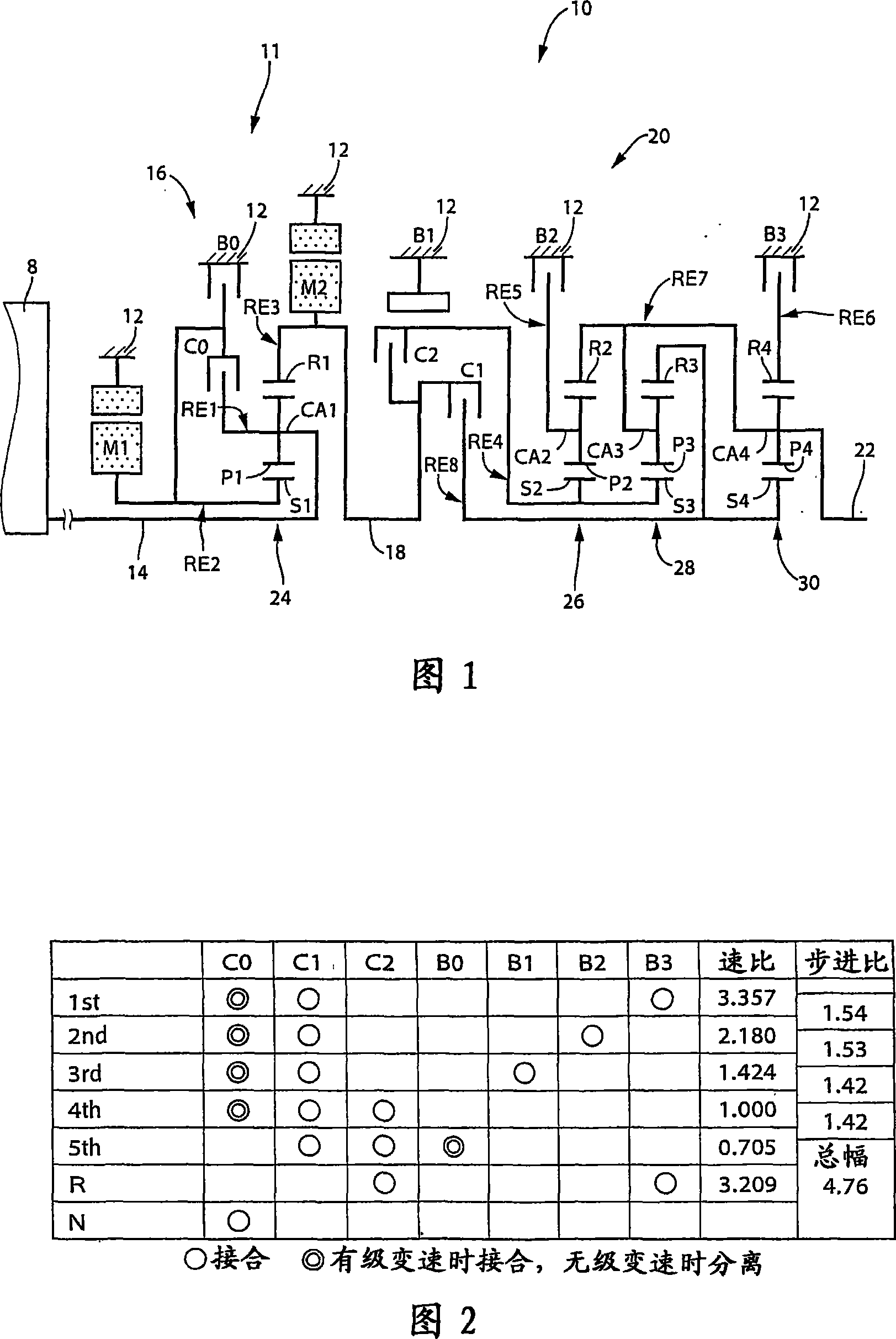
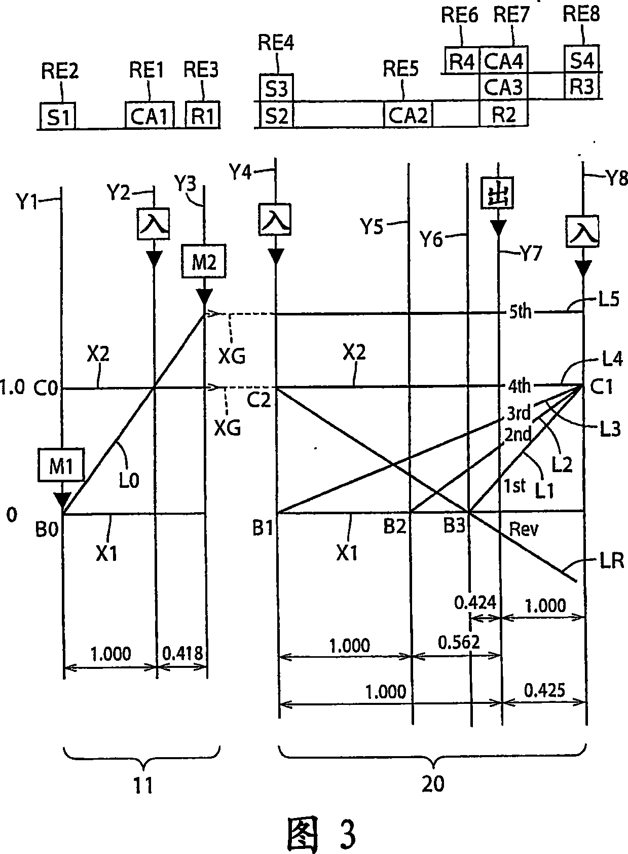
[0168] FIG. 1 is a skeleton diagram showing a speed change mechanism (ie, transmission mechanism) 10 constituting a part of a hybrid vehicle driving apparatus according to an embodiment of the present invention. A transmission mechanism (ie, transmission mechanism) 10 includes an input shaft 14, a differential portion 11, an automatic transmission portion 20, and an output shaft 22, all of which are coaxially arranged in a transmission case 12 as a non-rotatable member fixed to a vehicle body. (hereinafter referred to as "housing 12"). An input shaft 14 as an input rotating member is fixed to the housing 12 . A differential portion 11 functioning as a continuously variable transmission portion is directly or indirectly connected to an input shaft 14 via an unillustrated pulsation absorbing damper (vibration damper). An automatic transmission portion 20 (ie, an automatic transmission portion functioning as a stepped transmission) is disposed between the differential mechanism ...
Embodiment 2
[0427] FIG. 20 is a skeleton diagram illustrating the structure of a transmission mechanism 70 according to another embodiment of the present invention. The actuation of FIG. 21 shows the relationship between the actuation combination of the shift stage of the transmission mechanism 70 and the hydraulic friction engagement device used therefor. The nomographic diagram of FIG. 22 illustrates the shifting operation of the shifting mechanism 70 .
[0428] Like the above-mentioned embodiment, the transmission mechanism 70 includes a differential portion 11 and an automatic shift portion 72, the differential portion 11 includes a first electric motor M1, a power distribution mechanism 16, and a second electric motor M2, and the automatic shift portion 72 communicates with the differential through the transmission member 18. Section 11 and output shaft 22 are connected in series and have three forward gears. The power distributing mechanism 16 includes a first planetary gear unit 2...
Embodiment 3
[0443] FIG. 23 shows an example of an interactive switch 44 (hereinafter referred to as "switch 44") as shift state manual selection means, which is mounted on a vehicle and manually operated by a vehicle driver. The switch 44 allows manual operation to selectively place the power distributing mechanism 16 into a differential state and a non-differential state (locked state), that is, the continuously variable state and the stepped state of the transmission mechanism 10 . Switch 44 allows the vehicle to travel in the shift state desired by the driver of the vehicle. The switch 44 has: a continuously variable speed change driving command button, on which "stepless" is displayed, indicating a continuously variable speed change driving mode; . When the driver of the vehicle presses one of these buttons, the transmission mechanism 10 is selectively placed in a continuously variable transmission state operable as an electronically controlled continuously variable transmission or a...
PUM
 Abstract
Description
Claims
Application Information
 - R&D
- Intellectual Property
- Life Sciences
- Materials
- Tech Scout
- Unparalleled Data Quality
- Higher Quality Content
- 60% Fewer Hallucinations
Browse by: Latest US Patents, China's latest patents, Technical Efficacy Thesaurus, Application Domain, Technology Topic, Popular Technical Reports.
© 2025 PatSnap. All rights reserved.Legal|Privacy policy|Modern Slavery Act Transparency Statement|Sitemap|About US| Contact US: help@patsnap.com


