
Building installation unit identification system and method

A technology for installing units and identifying systems, which is applied in the direction of collaborative devices, record carriers used by machines, instruments, etc., to achieve intelligent loading and unloading, improve the degree of informatization, and avoid the effects of installing units

Pending Publication Date: 2017-06-13
CHINA GEZHOUBA GRP THREE GORGES CONSTR ENG CO LTD
View PDF13 Cites 1 Cited by
  • Summary
  • Abstract
  • Description
  • Claims
  • Application Information

AI Technical Summary

Problems solved by technology

[0004] There is no better record in the prior art for the installation and identification of such large structures

Method used


Image

  • Building installation unit identification system and method
  • Building installation unit identification system and method
  • Building installation unit identification system and method

Examples


Embodiment 1

[0035] Such as Figure 5 , 6 Among them, a building installation unit identification system, including an electronic tag 1 fixed on each installation unit, a unit router 2 corresponding to a plurality of electronic tags, used to read the electronic tag 1 and communicate with the unit router 2 Terminal 3;

[0036] The unit router 2 is provided with an electronic tag reader and network components, and the terminal 3 is provided with an electronic tag reader, a computing unit and network components. . Due to the limited recognition distance of the electronic tag 1, in order to improve the recognition efficiency, a unit router 2 is set, so that the terminal 3 can quickly obtain the approximate positions of all installed units, which greatly improves the recognition efficiency and correspondingly improves the installation efficiency.

[0037] In a preferred solution, the electronic tag 1 is provided with a coupling coil, the coupling coil is connected to the chip, and the chip i...

Embodiment 2

[0043] Such as Figure 1~4 An identification method using the structure installation unit identification system in the above-mentioned embodiment 1, comprising the following steps:

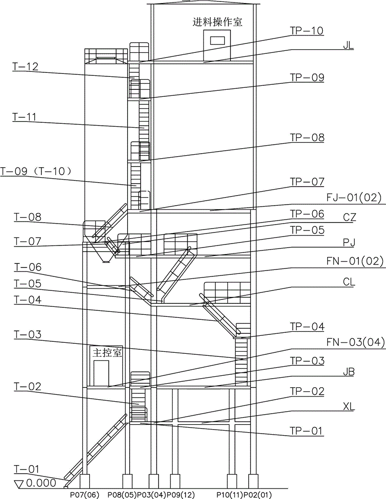
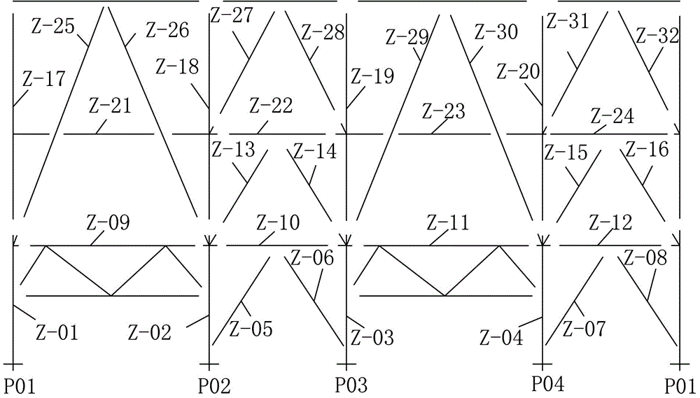
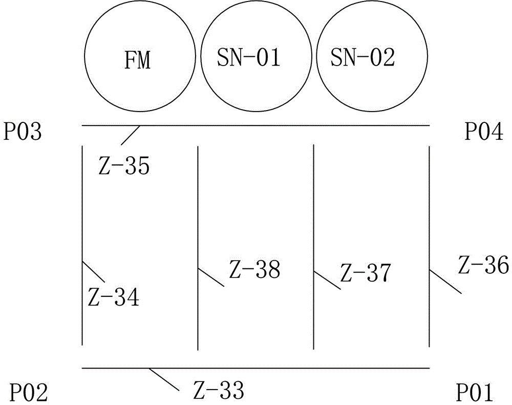
[0044] 1. Divide the structure into multiple installation units. In the preferred solution, the installation units are divided according to the functional layer, structural space, and component names of the structure. The installation units are assembled from ex-factory parts, subassemblies, and components. Able to use and work independently in an environment.

[0045] Each installation unit generates an independent code; taking the mixing plant structure as an example, such as Figure 1~3 In, the mixing plant is divided into multiple installation units. And compile the code, the code can use an independent code, and the independent code corresponds to the readable code in the database. In order to avoid failure of the electronic label 1 , a readable code is also printed on the electronic label...


PUM


Abstract

The invention provides a building installation unit identification system and method. The system comprises electronic tags fixed to installation units, a unit router corresponding to the electronic tags, and a terminal used for reading the electronic tags and communicating with the unit router, wherein an electronic tag reader and a network component are arranged in the unit router; and an electronic tag reader, a calculation unit and a network component are arranged in the terminal. The method comprises the steps of dividing a building into the installation units, wherein each installation unit generates an independent code; inputting the independent codes to the electronic tags, and fixing the electronic tags to the installation units; forming a group by the installation units to correspond to the unit router; and reading the electronic tags and communication information of the terminal and the unit router through the terminal to guide uninstallation, transport and installation of the building. Through different schemes for grouping different data, intelligent installation and uninstallation can be realized, so that the construction efficiency is greatly improved. The building installation unit identification system and method can be used for detecting installation quality.

Description

technical field [0001] The invention relates to the field of installation of large structures, in particular to a system and method for identifying installation units of structures. Background technique [0002] With the continuous expansion of the construction scale of various projects, the concrete mixing plant is more and more favored by customers because of its high production efficiency, high degree of automation and good product quality. This machine, which can continuously produce mass concrete, is mainly composed of two parts: steel structure and equipment in the building. The steel structure is the frame that supports the equipment, concrete raw materials, finished materials and its own weight in the building. It is generally divided into main and auxiliary building steel structures, which are composed of multiple installation units connected by high-strength bolts or pin shafts. The mechanical and electrical equipment in the building are the main body of the concr...

Claims


Application Information

Patent Timeline
Patent Type & Authority Applications(China)
IPC IPC(8): G06K17/00G06K19/077
CPCG06K17/0022G06K19/077
Inventor 蔡广毡刘翠娟杨建强余红玲代慧马斌王诗杰周靖郝洁隗露范凌天杨毕凤
Owner CHINA GEZHOUBA GRP THREE GORGES CONSTR ENG CO LTD
Learn More