
A liquid crystal display and its driving method

A liquid crystal display and liquid crystal layer technology, applied in static indicators, instruments, nonlinear optics, etc., can solve the problems of polarizer loss, difficulty in saving energy, and difficulty in making it lighter and thinner, so as to reduce thickness and power consumption Effect

Active Publication Date: 2020-11-17
BOE TECH GRP CO LTD
View PDF5 Cites 0 Cited by
  • Summary
  • Abstract
  • Description
  • Claims
  • Application Information

AI Technical Summary

Problems solved by technology

[0004] It can be seen that the stacked structure of the upper and lower polarizers in the existing liquid crystal display device structure limits the thickness of the liquid crystal display device, making it difficult to achieve a lighter and thinner purpose; in addition, the use of polarizers consumes at least 50% of light energy, only It can rely on increasing the brightness of the backlight to meet the brightness requirements of the liquid crystal display device, which undoubtedly increases the power consumption of the liquid crystal display device, and it is difficult to achieve more energy-saving purposes

Method used


Image

  • A liquid crystal display and its driving method
  • A liquid crystal display and its driving method
  • A liquid crystal display and its driving method

Examples


Embodiment Construction

[0040] In order to make the purpose, technical solutions and advantages of the present invention clearer, the present invention will be further described in detail below in conjunction with the accompanying drawings. Obviously, the described embodiments are only some of the embodiments of the present invention, rather than all of them. Based on the embodiments of the present invention, all other embodiments obtained by persons of ordinary skill in the art without making creative efforts belong to the protection scope of the present invention.

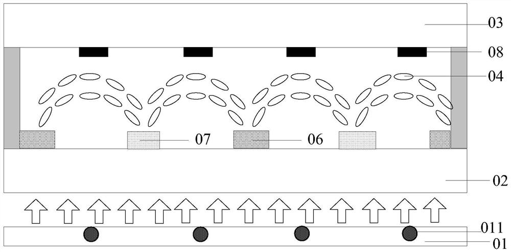
[0041] Embodiments of the present invention provide a liquid crystal display and a driving method thereof, which are used to reduce the use of upper and lower polarizers in a traditional liquid crystal display, so as to achieve the purpose of thinner and lighter liquid crystal display devices and energy saving.

[0042] The shapes and sizes of the components in the drawings do not reflect the real scale, but are only intended to schemati...


PUM


Abstract

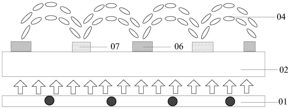
The invention discloses a liquid crystal display and a driving method thereof, which are used for reducing the use of upper and lower polarizers in the traditional liquid crystal display, so as to achieve the purpose of thinner and lighter liquid crystal display devices and energy saving. The liquid crystal display includes a backlight, a lower substrate located on the light-emitting side of the backlight, an upper substrate opposite to the lower substrate, and a liquid crystal layer located between the upper substrate and the lower substrate, and also includes: between the lower substrate and the liquid crystal layer The first electrode and the second electrode arranged in the same layer and arranged at intervals, and the control unit for applying voltage to the first electrode and the second electrode; wherein, the light on the light output side of the backlight is collimated and incident into the liquid crystal layer; in the display , the first electrode and the second electrode are used to control the deflection of the liquid crystal molecules in the corresponding area of ​​the liquid crystal layer to form a convex lens structure; the control unit is used to adjust the voltage of each first electrode and the second electrode to control the formed lens curvature of the structure.

Description

technical field [0001] The invention relates to the technical field of liquid crystal display, in particular to a liquid crystal display and a driving method thereof. Background technique [0002] With the rapid development of technology in the display field, people have higher and higher requirements for display devices. Thin and light, energy-saving has always been the development goal of display devices. [0003] The display principle of the existing liquid crystal display panel is to convert natural light into linearly polarized light through the polarizer on the array substrate, apply voltage to the pixel electrode and the common electrode to form an electric field on both sides of the liquid crystal layer, and the liquid crystal molecules in the liquid crystal layer are under the action of the electric field Rotation occurs, thereby changing the polarization state of the linearly polarized light. The polarizer on the color filter substrate then analyzes it, and the po...

Claims


Application Information

Patent Timeline
Patent Type & Authority Patents(China)
IPC IPC(8): G09G3/36G02F1/1343
CPCG02F1/134363G09G3/36G02F1/133512G09G3/3611G02F1/294G02F1/133514G02F1/133526G02F1/133602G02F1/1337G09G3/3607
Inventor 牛小辰董学陈小川赵文卿陈祯祐王海燕
Owner BOE TECH GRP CO LTD
Learn More