Centralized charging and discharging system and centralized charging and discharging control method and device

A charging and discharging, centralized technology, applied in circuit devices, battery circuit devices, charging stations, etc., can solve problems such as high maintenance costs, inability to coordinate output power, and inability to solve grid electricity congestion.

Inactive Publication Date: 2017-06-13
GLOBAL ENERGY INTERCONNECTION RES INST EURO GMBH +3
View PDF6 Cites 7 Cited by
  • Summary
  • Abstract
  • Description
  • Claims
  • Application Information

AI Technical Summary

Problems solved by technology

[0004] Therefore, the technical problem to be solved by the embodiment of the present invention is that the design of the charging station in the prior art is based on the mode of one charging pile and one charging connector, and each DC charging pile in...

Method used


Image

  • Centralized charging and discharging system and centralized charging and discharging control method and device
  • Centralized charging and discharging system and centralized charging and discharging control method and device
  • Centralized charging and discharging system and centralized charging and discharging control method and device

Examples


Embodiment 1

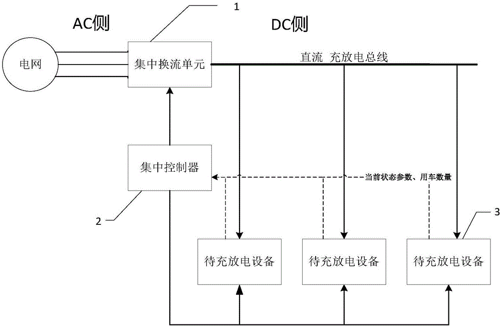
[0066] This embodiment provides a centralized charging and discharging system, such as figure 1 As shown, it includes: a centralized converter unit 1, whose input end is connected to the power grid, and whose output end is connected to the charging and discharging bus for outputting direct current; the charging and discharging bus is connected to one or more charging and discharging branches; the charging and discharging device 3, Set on each charging and discharging branch; the centralized controller 2 is connected to the centralized commutation unit 1 and the equipment to be charged and discharged 3 respectively, and is used to coordinate and control the output power of the centralized commutation unit 1 and control the equipment to be charged and discharged 3 to perform charging. Discharge work, and receive the current state parameters and the number of vehicles returned by the charging and discharging device 3. The centralized controller 2 here can be regarded as a hub for ...

Embodiment 2

[0075] This embodiment provides a centralized charging and discharging control method, such as Figure 4 As shown, the centralized controller applied to the centralized charging and discharging system in Embodiment 1 includes:

[0076] S1. Establish a connection with the equipment to be charged and discharged and the centralized converter unit; realize the transmission of information by establishing a connection with the equipment to be charged and discharged and the centralized converter unit by using one or more of the optical fiber network, automotive CAN bus or wireless transmission methods , to realize the control of the topology of the Internet of Things.

[0077] S2. Obtain the state parameters and the number of vehicles of the current equipment to be charged and discharged; mentioned in embodiment 1 that the state parameters are the current identity, current time, and current operating electrical parameters of the battery of the equipment to be charged and discharged. ...

Embodiment 3

[0094] This embodiment provides a centralized charge and discharge control device, such as Image 6 As shown, it is used in the centralized controller in embodiment 1, corresponding to the centralized charging and discharging control method in embodiment 2, including:

[0095] The first connection module 61 is used to establish a connection with the equipment to be charged and discharged and the centralized commutation unit;

[0096] The first acquisition module 62 is used to acquire the state parameters and the number of vehicles currently to be charged and discharged;

[0097] The establishment and prediction module 63 is used to establish the power model of the equipment to be charged and discharged according to the multiple data storage records obtained in advance, and predict the number of vehicles used in the later period;

[0098] The second acquisition module 64 is configured to acquire electrical parameters of the grid state;

[0099] A determination module 65, conf...


PUM


Abstract

The invention discloses a centralized charging and discharging system and a centralized charging and discharging control method and device, wherein the centralized charging and discharging system comprises a centralized commutation unit, devices to be charged or discharged and a centralized controller; the input end of the centralized commutation unit is connected with a power network, and the output end of the centralized commutation unit is connected with a charging and discharging bus. One or multiple charging and discharging branches are connected with the charging and discharging bus. The devices to be charged or discharged are arranged on the charging and discharging branches respectively. The centralized controller is connected with the centralized commutation unit and the devices to be charged or discharged respectively. Unified commutation, unified control and unified management are achieved by means of the centralized commutation unit and the centralized controller. Since the centralized commutation unit is designed collectively, it is not necessary to provide a plurality of discrete commutation devices, thus reducing excessive power investment and maintenance costs, further connecting with the power network and commercial platforms, and improving the coordination work of the power network and the commercial management of electricity market. The centralized charging and discharging system and the centralized charging and discharging control method and device not only meet the needs of users, but also ensure stable power output of the power network. The problem of electricity congestion of the power network is solved by the coordinated control over the devices to be charged or discharged.

Description

technical field [0001] The invention relates to the technical field of charging and discharging, in particular to a centralized charging and discharging system, a control method and a device. Background technique [0002] As the country vigorously promotes green travel, the development of electric vehicles has been highly valued by the state and enterprises. Because of the implementation of the "Twelfth Five-Year Plan", the government also advocates energy-saving policies and has begun to vigorously build charging facilities or design charging systems for electric vehicles. Energy, and steadily implement the development of new energy electric vehicles or other electric vehicles. [0003] At present, the charging and discharging system of electric vehicles on the market is generally designed on charging stations in public buildings or residential areas, and the design of charging stations is mostly based on the model of one charging pile and one charging connector. A single D...

Claims


Application Information

Patent Timeline
IPC IPC(8): H02J7/00B60L11/18
CPCB60L53/60H02J7/0019Y02T10/70Y02T10/7072Y02T90/12
Inventor 雷宪章冯义兰天周育桢
Owner GLOBAL ENERGY INTERCONNECTION RES INST EURO GMBH
Why Eureka
Try Eureka