
Wide angle camera shooting system

A wide-angle camera and camera technology, applied in the field of wide-angle camera systems, can solve the problems of incapable of real-time acquisition and monitoring, complex structure, inconvenient popularization, etc., and achieve the effect of enhancing the realism of the picture, simple overall structure, and real-time dynamic display

Pending Publication Date: 2017-06-13
惠州市世纪佳华电子科技有限公司
View PDF10 Cites 5 Cited by
  • Summary
  • Abstract
  • Description
  • Claims
  • Application Information

AI Technical Summary

Problems solved by technology

However, part of the current panoramic camera is not easy to popularize due to its complex structure and high cost; the other part uses a turntable to achieve wide-angle shooting. Although the cost is greatly reduced, due to the limitation of image processing technology, it is easy to cause image delay and cannot be collected in real time. Dynamic scene with monitoring

Method used


Image

  • Wide angle camera shooting system

Examples


Embodiment 1

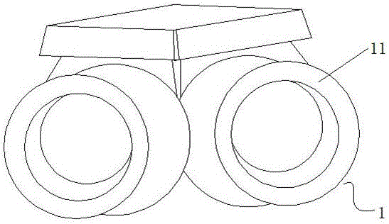
[0022] see figure 1 , a wide-angle camera system comprising:

[0023] The imaging assembly 1 includes two image heads 11 with an included angle of 60 degrees;

[0024] The image processing unit includes an image processing chip connected with the above-mentioned camera signal and provided with an image splicing module.

[0025] In this embodiment, a video signal output component is also included, including a display for outputting and displaying the image signals spliced ​​and parsed by the image processing unit.

[0026] Since the imaging assembly of the present invention is provided with two cameras, and the cameras form a certain angle, each camera has a collection and shooting range of about 100 degrees; the scientific combination of the two cameras forms a collection and shooting range of about 200 degrees. range, realize wide-angle photography, and break through the limitation of the camera's shooting range.

[0027] Wherein, the above-mentioned included angle in this...

Embodiment 2

[0033] This embodiment discloses a wide-angle camera system, including:

[0034] Imaging assembly, including two cameras with an included angle of 45 degrees;

[0035] The image processing unit includes an image processing chip connected with the above-mentioned camera signal and provided with an image splicing module.

[0036] Since the imaging assembly of the present invention is provided with two cameras, and the cameras form a certain angle, each camera has a collection and shooting range of about 100 degrees; the scientific combination of the two cameras forms a collection and shooting range of about 200 degrees. range, realize wide-angle photography, and break through the limitation of the camera's shooting range.

[0037] Wherein, the above-mentioned included angle in this embodiment is set at an angle of 45 degrees. This is because the inventors have learned through in-depth research on the principles of imaging and mechanical structure that when the angle between th...


PUM


Abstract

The invention discloses a wide angle camera shooting system. The wide angle camera shooting system comprises an imaging assembly, a picture processing unit, and a video signal outputting assembly, wherein the imaging assembly comprises two cameras which share one certain included angle, the picture processing unit comprises a picture processing chip which is in signal connection to the cameras and is provided with a picture jointing module. The video signal outputting assembly comprises a display which is used for outputting and displaying a picture signal which is jointed and analyzed by the picture processing unit. The included angle is set to be 15-85 degrees. The wide angle camera shooting system is simple in structure, dual cameras are adopted for view taking and imaging, a picture synthesis technology of a software algorithm is adopted to conduct seamless jointing to obtain a full-view wide-width picture, and the problems that a traditional single 360-degree full view camera can easily result in picture delaying and cannot collect and monitor dynamic scenes in real time, and dead angle and dead zones exist when the single 360-degree full view camera is utilized in a vehicle are solved.

Description

technical field [0001] The invention belongs to the technical field of cameras, and in particular relates to a wide-angle camera system. Background technique [0002] As a real-time image and video acquisition device, cameras are widely used in video conferences, telemedicine, and real-time monitoring. The general public can also conduct images, audio conversations and communication on the network through cameras. Especially since the integration of camera technology and automobiles, practical security products such as driving recorders and in-vehicle monitoring equipment have become popular. With the continuous development of science and technology, there are many types of camera devices used in vehicles currently on the market, but most of the cameras have not wide enough shooting angles, which limits their performance. The innovation of computer image processing and image synthesis technology has brought a wide variety of panoramic cameras. However, part of the current ...

Claims


Application Information

Patent Timeline
Patent Type & Authority Applications(China)
IPC IPC(8): H04N5/225G02B13/06G02B13/18G06T3/40G06T5/00
CPCG02B13/06G02B13/18G06T3/4038H04N23/55G06T5/00
Inventor 王伟
Owner 惠州市世纪佳华电子科技有限公司
Learn More