Diamond cutting tool welding machine and matrix position control method

A diamond cutting and welding machine technology, applied in diamond cutting tool welding machine, diamond cutting tool welding machine substrate position control, welding field, can solve the problems that affect the processing efficiency, take up a lot of time, can not guarantee the quality of brazing, etc., to achieve The effect of ensuring the consistency of welding quality and improving the efficiency of welding processing

Active Publication Date: 2017-06-20
项俊俊
View PDF8 Cites 9 Cited by
  • Summary
  • Abstract
  • Description
  • Claims
  • Application Information

AI Technical Summary

Problems solved by technology

However, the above methods all have the following deficiencies. 1. The position of each diamond cutting tool needs to be adjusted once, so there is a problem that the adjustment process takes too much time and affects the processing efficiency; 2. The accuracy of manual adjustment is low and cannot be adjusted. To ensure the quality of brazing, it is necessary to test the welding strength of each piece

Method used


Image

  • Diamond cutting tool welding machine and matrix position control method
  • Diamond cutting tool welding machine and matrix position control method
  • Diamond cutting tool welding machine and matrix position control method

Examples


Embodiment 1

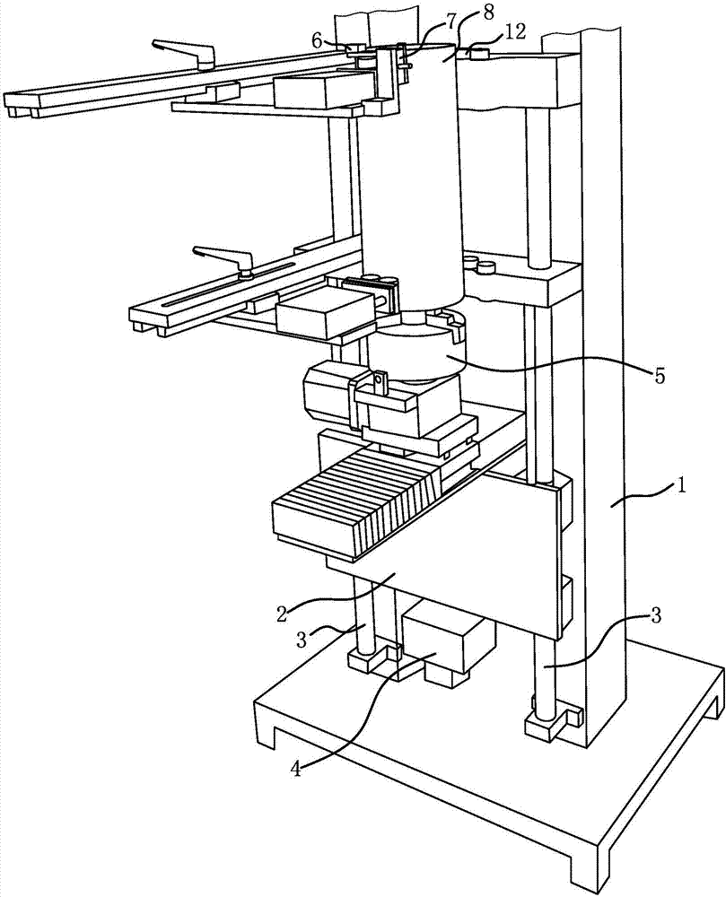
[0023] The diamond cutting tool welding machine comprises a frame 1, a lifting plate 2, a clamping mechanism 12 at the top of a substrate and a control circuit.

[0024] The lifting plate 2 and the frame 1 are connected through the vertical guide rail 3, the motor 4 is installed on the frame 1, and the mechanical transmission structure that can make the lifting plate 2 move along the vertical guide rail 3 is passed between the motor 4 and the lifting plate 2 Connected; the mechanical transmission structure includes a screw mandrel connected with the rotating shaft of the motor 4 and a screw nut fixedly connected with the lifting plate 2, the screw mandrel and the screw nut are threaded, that is, the rotation of the main shaft of the motor 4 can force the lifting plate 2 to move up and down.

[0025] A base body positioning structure 5 is installed on the lifting plate 2; the base body positioning structure 5 is determined according to the type of the diamond cutting tool. The ...

Embodiment 2

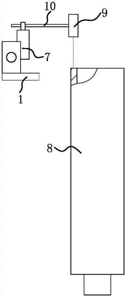
[0031] The structure and principle of this embodiment are basically the same as that of Embodiment 1, and the basic similarities will not be redundantly described, and only the differences will be described, and the differences are as follows: image 3 As shown, the electronic sensing element is a distance measuring sensor 9, and the distance measuring sensor 9 is connected to the frame 1 through a height-adjustable sliding table 7 and a swing rod 10, and the base of the height-adjustable sliding table 7 is fixed to the frame 1 Connect, fork 10 is arranged horizontally, and one end of fork 10 is rotatably connected with the lifting slide table of height-adjustable slide table 7, and the other end of fork 10 is fixedly connected with distance measuring sensor 9. In this way, the height of the distance measuring sensor 9 can be flexibly adjusted according to the position of the heating tube of the high-frequency machine, and the horizontal position of the distance measuring senso...

Embodiment 3

[0034] The structure and principle of this embodiment are basically the same as that of Embodiment 1, and the basic similarities will not be redundantly described, and only the differences will be described, and the differences are as follows: Figure 4 As shown, the diamond cutting tool welding machine is used for welding the diamond segment circular saw blade, the high frequency welding machine is located on one side of the substrate of the diamond segment circular saw blade, and the photoelectric sensor 6 is located on the other side of the diamond segment circular saw blade substrate 11 . The point to be welded on the diamond segment circular saw blade base 11 is the apex of the base, then the position of the light emitted by the photoelectric sensor 6 is perpendicular to the plate surface of the diamond segment circular saw blade base 11 and is at the top of the diamond segment circular saw blade base 11. Corresponding.


PUM


Abstract

The invention provides a diamond cutting tool welding machine and a matrix position control method, and belongs to the technical field of machine tools. The diamond cutting tool welding machine and the matrix position control method solve the problems that the position of a j matrix of a diamond cutting tool needs to be adjusted once every time an existing diamond cutting tool welding machine machines one diamond cutting tool, and consequently the machining efficiency is influenced. The diamond cutting tool welding machine comprises a rack and a lifting plate. An electronic sensing element used for monitoring whether a to-be-welded point of a matrix is located at a set welding position or not is further mounted on the rack. The diamond cutting tool welding machine further comprises a control circuit, and the electronic sensing element and a motor are both electrically connected with the control circuit. When a diamond cutting tool is welded, the actual position of the to-be-welded point of the matrix is located below the set welding position, the control circuit controls a spindle of the motor to continuously rotate till the electronic sensing element monitors that the position of the to-be-welded point of the matrix is consistent with the set welding position, and the control circuit controls the motor to stop rotating according to a monitor signal of the electronic sensing element.

Description

technical field [0001] The invention belongs to the technical field of machine tools and relates to welding, in particular to a diamond cutting tool welding machine. [0002] The invention belongs to the technical field of machine tools, and relates to welding, in particular to a method for controlling the base body position of a diamond cutting tool welding machine. Background technique [0003] Diamond-tipped thin-wall drills, diamond-tipped circular saw blades and diamond-tipped gang saws are common diamond cutting tools. Diamond cutting tools all comprise substrate and the diamond cutter head that is brazed on the substrate; In order to improve welding efficiency and welding quality, people have designed diamond cutting tool welding machine, as the cutter head clamping and positioning device of Chinese patent literature record (authorized announcement No. CN201211301Y), diamond tool welding machine (authorized announcement No. CN103223538A). [0004] When using a weldi...

Claims


Application Information

Patent Timeline
Patent Type & Authority Applications(China)
IPC IPC(8): B23K37/00B23K101/20
CPCB23K37/00B23K2101/20
Inventor 项俊俊
Owner 项俊俊
Why Eureka
Try Eureka