Wheel hub motor driving device

A driving device, in-wheel motor technology, applied in power devices, control devices, motion deposition, etc., can solve problems that are not conducive to improving the motor power density, the quality of the in-wheel motor driving device, the reduction of the unsprung mass of the in-wheel motor driving device, and the large motor torque. and other problems, to achieve the effect of being conducive to heat dissipation, simple structure and increasing speed

Active Publication Date: 2017-06-20
BEIJING INSTITUTE OF TECHNOLOGYGY
View PDF14 Cites 25 Cited by
  • Summary
  • Abstract
  • Description
  • Claims
  • Application Information

AI Technical Summary

Problems solved by technology

[0003] CN103434385A, CN105305713A and CN105656246A all announced the single-stage planetary gear reducer for the hub motor driver, but the reduction ratio is small. Under the same vehicle speed and wheel diameter, the motor speed is low, which is not conducive to improving the power density of the motor and reducing the hub motor drive. Quality of the device
The structure of the single-stage planetary reducer is simple, but the reduction ratio obtained is limited, and the torque of the required motor is large, which is not conducive to the reduction of the unsprung mass of the hub motor drive device

Method used


Image

  • Wheel hub motor driving device
  • Wheel hub motor driving device
  • Wheel hub motor driving device

Examples


Embodiment 1

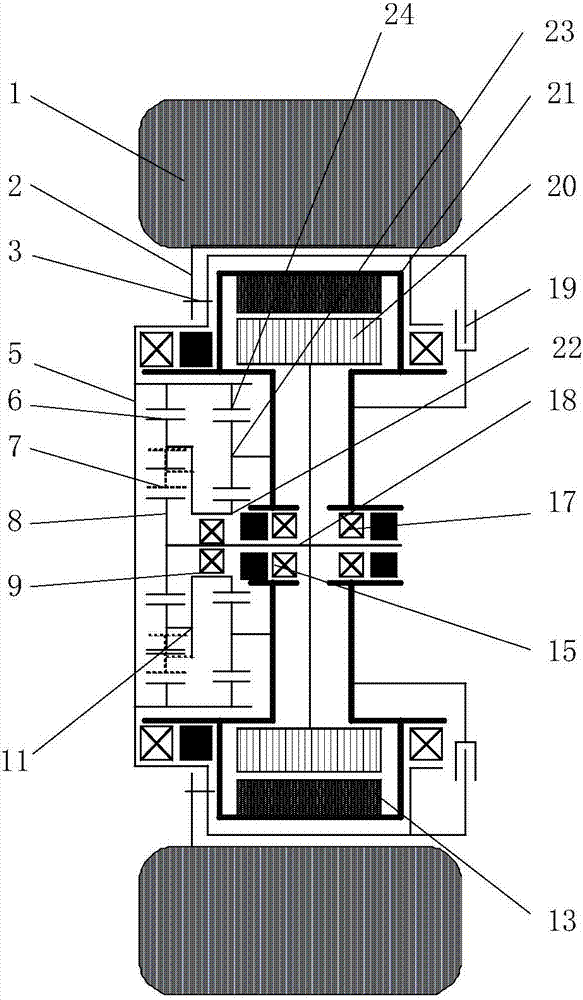
[0022] Embodiment 1: A wheel hub motor drive device, which includes: a housing 21, a motor, a two-stage planetary reducer, a rim 2, and a tire 1;

[0023] The inner side of the housing 21 is arranged with a steering system, a suspension system, a motor cable and a cooling system;

[0024] The motor includes: stator 13, rotor 20, and output shaft 18; the stator 13 is fixedly connected to the inner side of the housing 21, and the rotor 20 transmits the power of the motor to the two-stage planetary reducer through the output shaft 18 arranged on the motor bearings 15 and 17 ;

[0025] The motor and the two-stage planetary reducer are coaxially arranged, and the two-stage planetary reducer includes: an internal and external meshing planetary row composed of the first planet carrier 11, the first ring gear 6, the first planetary gear 7, and the first sun gear 8, and A planetary row composed of the second planet carrier 23, the second ring gear 24, and the second sun gear 22; the s...

Embodiment 2

[0027] Embodiment 2: see attached figure 1 , on the basis of Embodiment 1, add a brake 19 arranged coaxially with the motor and the two-stage planetary reducer; the brake 19 is installed on the inner side of the output end 5 of the two-stage planetary reducer close to the direction of the vehicle body, and the brake caliper and the shell Body 21 is fixed together.

Embodiment 3

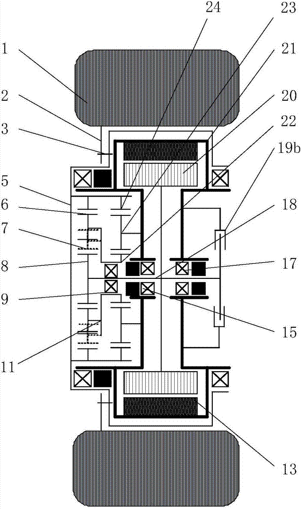
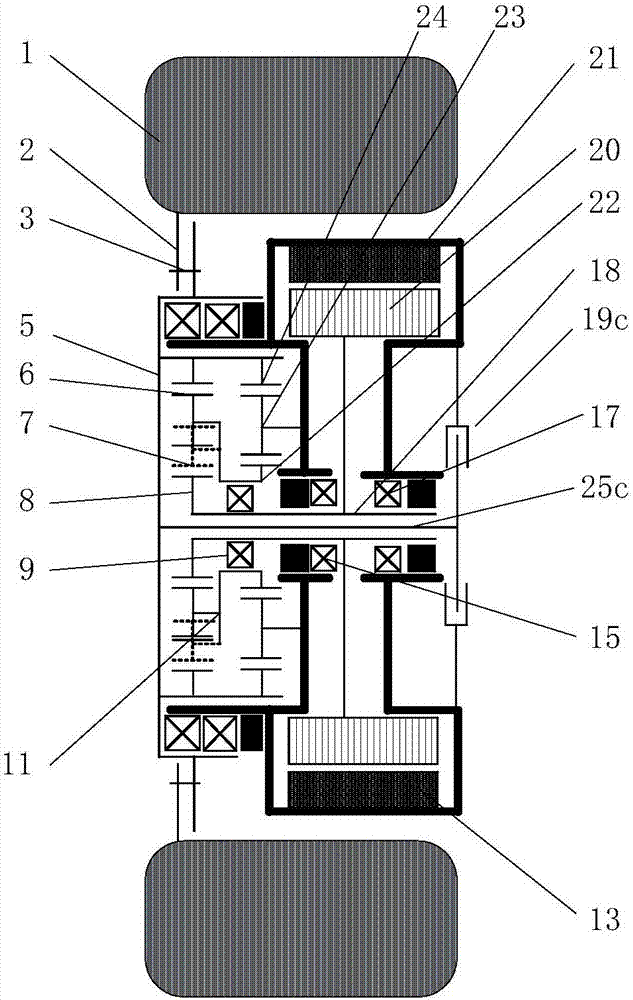
[0028] Embodiment 3: see attached figure 2 , on the basis of Embodiment 1, increase the brake 19b arranged coaxially with the motor and the two-stage planetary reducer; the brake 19b is fixedly connected to the output shaft 18 of the motor, and the brake caliper is connected to the housing 21; The planetary reducer is amplified, so the braking torque is small, and the diameter of the brake 19b is relatively small.


PUM


Abstract

The invention belongs to the technical field of electric cars and particularly relates to a power transmission technology. A wheel hub motor driving device comprises a shell (21), a motor, a two-stage planetary reducer, wheel rims (2) and tires (1); and the motor and the two-stage planetary reducer are coaxially arranged, the wheel rims (2) are connected with the output end (5) of the two-stage planetary reducer, and the tires (1) are installed on the wheel rims (2), so that power from the two-stage planetary reducer is transmitted to the tires (1). According to the wheel hub motor driving device, a planetary reducing mechanism is adopted, the manufacturability is good, transmission efficiency is high, the large transmission ratio can be obtained, the rotating speed of the motor can be increased, and thus the power density of the wheel hub motor driving device is improved; output of the reducer serves as a rotating shell and is directly connected with the wheel rims, and wheel detaching and installing are convenient; and brakes are arranged inside the wheels, the outer diameters are large, and thus heat dissipation and thermal capacity guaranteeing are facilitated.

Description

technical field [0001] The invention belongs to the technical field of electric vehicles, in particular to power transmission technology. Background technique [0002] CN103328247A, CN103026103A and CN102648362A respectively disclose three kinds of in-wheel motor drive devices, in which the torque of the inner rotor motor is amplified by a reducer to drive the wheels. In order to obtain a high reduction ratio, the reducer adopts a cycloid reducer with a compact structure. CN101852269A, CN105667296A and CN102076993A describe in detail the specific structure and implementation of the cycloid reducer. [0003] CN103434385A, CN105305713A and CN105656246A all announced the single-stage planetary gear reducer for the hub motor driver, but the reduction ratio is small. Under the same vehicle speed and wheel diameter, the motor speed is low, which is not conducive to improving the power density of the motor and reducing the hub motor drive. The quality of the device. [0004] Alt...

Claims


Application Information

Patent Timeline
Patent Type & Authority Applications(China)
IPC IPC(8): B60K7/00B60K17/04
CPCB60K7/0007B60K17/046
Inventor 彭增雄胡纪滨魏超
Owner BEIJING INSTITUTE OF TECHNOLOGYGY
Why Eureka
Try Eureka