
Enhanced hydroacoustic cavitation treatment device

A technology of treatment device and water inlet pipe, which is applied in special compound water treatment, water/sewage treatment, water/sewage treatment equipment, etc. Ideal and other issues, to achieve the effect of favorable degradation, improved treatment effect and low cost

Active Publication Date: 2020-06-30
SHAANXI NORMAL UNIV
View PDF4 Cites 0 Cited by
  • Summary
  • Abstract
  • Description
  • Claims
  • Application Information

AI Technical Summary

Problems solved by technology

[0006] As an early hydroacoustic cavitation generator, reed whistle brought a new method for acoustic cavitation purification water treatment, but the application of traditional reed whistle in sewage treatment was greatly limited, the most important The performance is: the number of free radicals generated is too small, especially the number of hydroxyl radicals is too small, resulting in unsatisfactory treatment of organic pollutants, so this method of sewage treatment has not been widely used in actual engineering

Method used


Image

  • Enhanced hydroacoustic cavitation treatment device
  • Enhanced hydroacoustic cavitation treatment device
  • Enhanced hydroacoustic cavitation treatment device

Examples


Embodiment 1

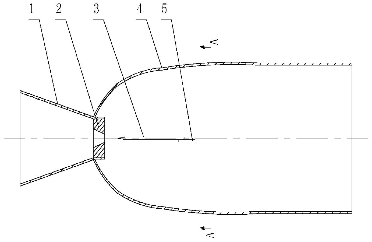
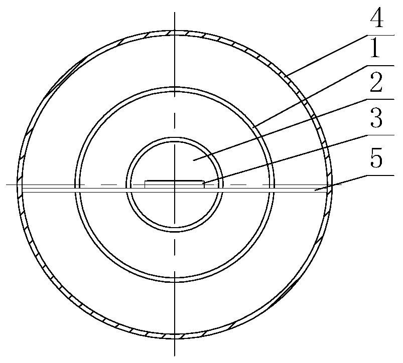
[0038] Depend on figure 1 and 2 It can be seen that the enhanced hydroacoustic cavitation treatment device of this embodiment includes a water inlet pipe 1 , a cavitation pipe 4 , a nozzle 2 , a reed 3 and a fixing plate 5 . Wherein, the inlet end of the water inlet pipe 1 communicates with the water inlet pump, the inner diameter of the inlet end is 60 mm, and the inner diameter of the outlet end is 48 mm. A nozzle 2 is set on the outlet end of the water inlet pipe 1, and the nozzle 2 extends to the inlet of the cavitation pipe 4, and a rectangular nozzle is processed on the outlet end surface of the nozzle 2, and the center line of the rectangular nozzle coincides with the central axis of the water inlet pipe 1, that is The rectangular spouts are distributed symmetrically on the center line of the water inlet pipe 1, the opening width h of the rectangular spouts is 1mm, and the length l is 24mm.

[0039] The water inlet pipe 1 and the cavitation pipe 4 are hermetically con...

Embodiment 2

[0048] Depend on Figure 6 and 7 It can be seen that the inner diameter of the inlet end of the water inlet pipe 1 of the present embodiment is 60mm, and the inner diameter of the outlet end is 48mm. A nozzle 2 is set on the outlet end of the water inlet pipe 1, and the nozzle 2 extends to the inlet of the cavitation pipe 4, and a rectangular nozzle is processed on the outlet end surface of the nozzle 2, and the center line of the rectangular nozzle coincides with the central axis of the water inlet pipe 1, that is The rectangular spouts are distributed symmetrically on the center line of the water inlet pipe 1, the opening width h of the rectangular spouts is 1mm, and the length l is 24mm.

[0049] The water inlet pipe 1 and the cavitation pipe 4 are hermetically connected, that is, the joint is filled with a sealing material to realize the hermetic connection.

[0050] Establish a coordinate system on the plane where the longitudinal section of the cavitation pipe 4 is loc...

Embodiment 3

[0061] Depend on Figure 8 and 9 It can be seen that the inlet end of the water inlet pipe 1 in this embodiment communicates with the water inlet pump, the inner diameter of the inlet end is 60mm, and the inner diameter of the outlet end is 48mm. A nozzle 2 is set on the outlet end of the water inlet pipe 1, and the nozzle 2 extends to the inlet of the cavitation pipe 4, and a rectangular nozzle is processed on the outlet end surface of the nozzle 2, and the center line of the rectangular nozzle coincides with the central axis of the water inlet pipe 1, that is The rectangular spouts are distributed symmetrically on the center line of the water inlet pipe 1, the opening width h of the rectangular spouts is 1mm, and the length l is 24mm.

[0062] The water inlet pipe 1 and the cavitation pipe 4 are hermetically connected, that is, the joint is filled with a sealing material to realize the hermetic connection.

[0063] Establish a coordinate system on the plane where the longi...


PUM

PropertyMeasurementUnit
thicknessaaaaaaaaaa
radiusaaaaaaaaaa
angleaaaaaaaaaa

Abstract

The invention relates to a strengthened hydraulic acoustic cavitation treatment device. The strengthened hydraulic acoustic cavitation treatment device comprises a water inlet pipe and a cavitation pipe communicated with the water inlet pipe; the outlet end of the water inlet pipe is designed to be convergent; a nozzle is arranged at the connection part of the water inlet pipe with the cavitation pipe; the center line of a nozzle opening of the nozzle and the center axis of the water inlet pipe are designed to be overlapped; a reed is arranged in the inner chamber of the cavitation pipe; the wedge point of the reed is arranged to face the nozzle opening of the nozzle directly. According to the strengthened hydraulic acoustic cavitation treatment device, the cross section of the cavitation pipe is designed to be a tapered cross section, jet flow is formed when water flows through a throat part, pulse stress is generated at the cross section, sound wave is generated, radiation of sound wave into the cavitation pipe is realized, when the wedge point of the reed is arranged at the focal point of a paraboloidal pipeline, radiation of sound wave into the cavitation pipe is realized, and sound wave passes through the cavitation pipe in parallel, so that sound wave radiation range is enlarged greatly, cavitation of liquid of a large range under the effect of sound wave is ensured, more strong free radicals are generated, it is beneficial for degradation of organic pollutants, and treatment effect is multiplied; operation and management are convenient; cost is low; and the technical structure is simple.

Description

technical field [0001] The invention belongs to the technical field of research on liquid fluid cavitation generating devices, and in particular relates to a hydroacoustic cavitation device for strengthening cavitation bubble collapse by using hydroacoustic cavitation to degrade organic pollutant wastewater. [0002] technical background [0003] All human activities are inseparable from water. Our human body is undergoing metabolism every day. During this process, various elements in the water will be brought into various parts of the human body through the digestive tract. If we use deteriorating water sources for a long time, it will inevitably lead to abnormal constitution, decreased resistance, and various diseases. disease. Relevant surveys show that 70% of diseases in my country are caused by poor drinking water quality. In recent years, "cancer villages" and "deformed villages" have been frequently exposed in various places, and various strange diseases frequently o...

Claims


Application Information

Patent Timeline
Patent Type & Authority Patents(China)
IPC IPC(8): C02F1/34C02F101/30
CPCC02F1/34C02F2101/30C02F2201/002C02F2305/02
Inventor 沈壮志
Owner SHAANXI NORMAL UNIV
Learn More