A kind of differential speed quenching device and process method of casting groove for mining scraper machine

The technology of a quenching device and process method, which is applied in the field of channel side casting, can solve the problems of inability to achieve hardness and performance, too fast wear of the channel side matrix, and insufficient toughness of the push ear, so as to shorten the holding time, improve the performance of the channel side, and improve Effect of mechanical properties and service life

Active Publication Date: 2019-07-30
山西煤矿机械制造股份有限公司
View PDF4 Cites 0 Cited by
  • Summary
  • Abstract
  • Description
  • Claims
  • Application Information

AI Technical Summary

Problems solved by technology

However, at present, the casting channel side only undergoes a single overall quenching and tempering heat treatment, the comprehensive mechanical properties are poor, and the reasonable distribution of hardness and performance cannot be realized. Often, the channel side matrix wears too fast due to low hardness, and the end breaks due to insufficient strength. , The moving ear is broken due to insufficient toughness

Method used


Image

  • A kind of differential speed quenching device and process method of casting groove for mining scraper machine
  • A kind of differential speed quenching device and process method of casting groove for mining scraper machine
  • A kind of differential speed quenching device and process method of casting groove for mining scraper machine

Examples


Embodiment 1

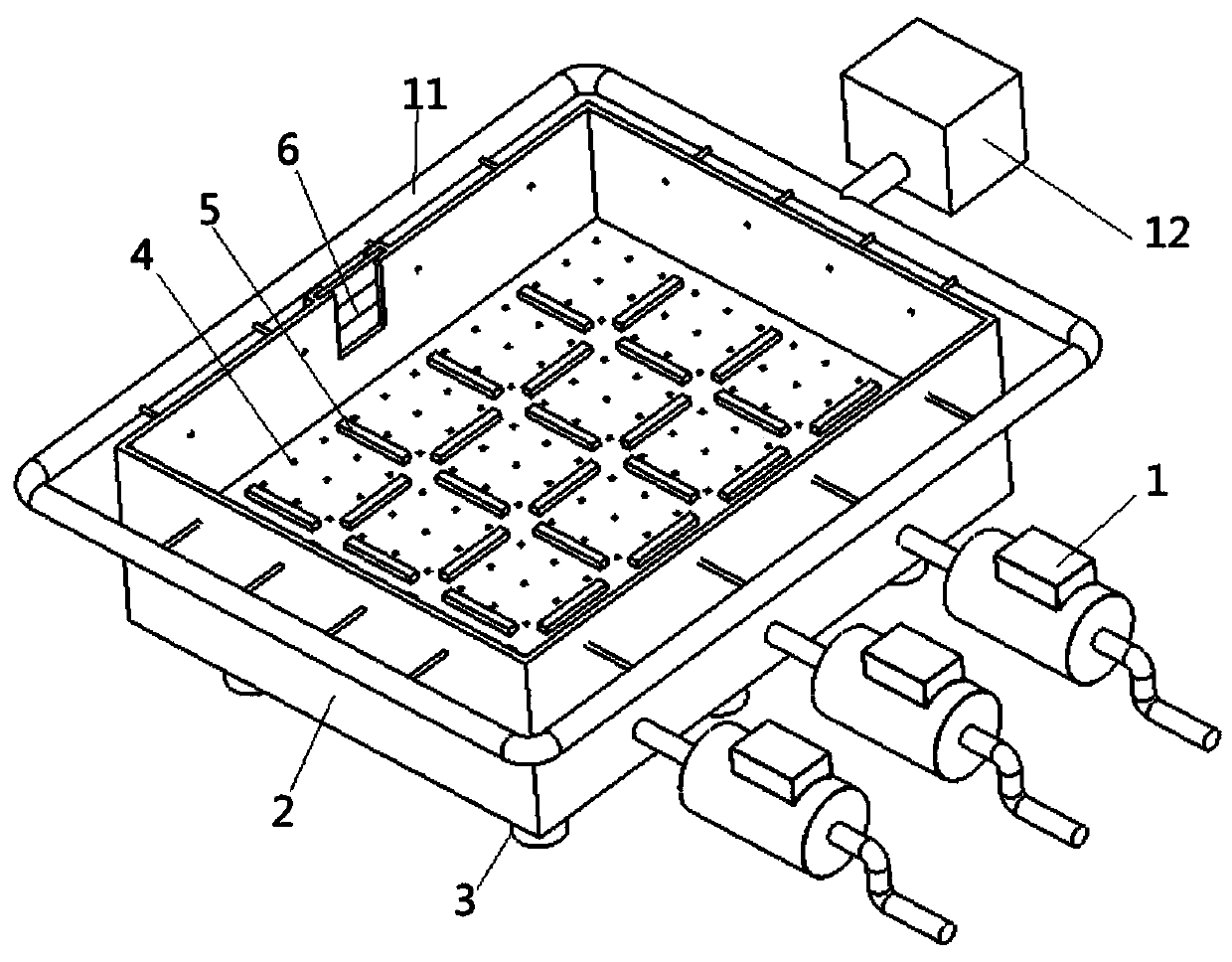
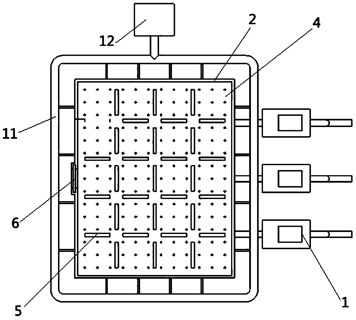
[0033] Embodiment 1: first turn on three water pumps, fill the water tank 2 with water, and set a water level partition 6 at the water outlet according to the height of the water quenching part of the side of the tank to determine the water level of the tank;

[0034] According to the height and shape of the water column formed by the hydraulic orifice plate, the flow and pressure of the water pump 1 are adjusted as long as the height of the water column does not exceed the water level of the tank;

[0035] When heating, heat the side of the tank in a resistance furnace, the holding temperature is 920°C, and after holding the heat for 90 minutes, it is quenched out of the furnace;

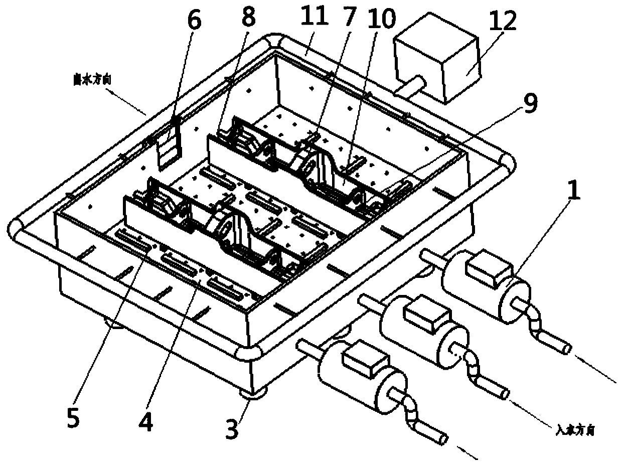
[0036] When quenching, the tank side is hoisted by pushing the 7 lugs upward, and slowly enter the water horizontally until the tank side base, convex end and concave end are all submerged in the water, and the water temperature during quenching is ≤30°C. The 7 parts of the moving ear are exposed t...

Embodiment 2

[0042] Embodiment 2: first turn on three water pumps, fill the water tank 2 with water, and set a water level partition 6 at the water outlet according to the height of the water quenching part of the side of the tank to determine the water level of the tank;

[0043] According to the height and shape of the water column formed by the hydraulic orifice plate, the flow and pressure of the water pump 1 are adjusted as long as the height of the water column does not exceed the water level of the tank;

[0044] Heating the side of the tank in a resistance furnace, the holding temperature is 920°C, and after holding the heat for 100 minutes, it is quenched out of the furnace;

[0045] When quenching, the side of the tank is hoisted with the push lug 7 facing upwards, and slowly enter the water horizontally until the base of the side of the tank, the convex end and the concave end are all submerged in the water, and the water temperature during the quenching process is ≤30°C. The 7 pa...

Embodiment 3

[0051] Embodiment 3: first turn on three water pumps, fill the water tank 2 with water, and set a water level partition 6 at the water outlet according to the height of the water quenching part of the side of the tank to determine the water level of the water tank;

[0052] According to the height and shape of the water column formed by the hydraulic orifice plate, the flow and pressure of the water pump 1 are adjusted as long as the height of the water column does not exceed the water level of the tank;

[0053] Heating the side of the tank in a resistance furnace, the holding temperature is 920°C, and after holding the heat for 120 minutes, it is quenched out of the furnace;

[0054] When quenching, the side of the tank is hoisted with the push lug 7 facing upwards, and slowly enter the water horizontally until the base of the side of the tank, the convex end and the concave end are all submerged in the water, and the water temperature during the quenching process is ≤30°C. ...


PUM

PropertyMeasurementUnit
tensile strengthaaaaaaaaaa
hardnessaaaaaaaaaa
tensile strengthaaaaaaaaaa

Abstract

The invention belongs to the technical field of ledge casting and particularly relates to a sectionalized differential quenching device and process method for a mine scraper blade machine casting ledge. The sectionalized differential quenching device for the mine scraper blade machine casting ledge comprises water pumps and a water trough. A waterpower hole plate is arranged in the water trough, water outlet holes are evenly distributed in the waterpower hole plate, and a plurality of supporting strips are arranged on the waterpower hole plate. The waterpower hole plate divides the water trough into an upper layer and a lower layer. The lower layer of one side wall of the water trough is provided with at least one water inlet, and each water inlet is correspondingly connected with one water pump. The upper layer of the side wall of the water trough is provided with a water outlet, and a water level adjusting device is arranged at the position of the water outlet. The sectionalized differential quenching device for the mine scraper blade machine casting ledge is convenient to operate, the process is advanced and reasonable, the ledge performance is improved, meanwhile, the quenching temperature is improved, the temperature keeping time is shortened, grains are refined, the production efficiency is improved, and the electric energy is saved.

Description

technical field [0001] The invention belongs to the technical field of channel side casting, and in particular relates to a mine-used scraper machine casting channel side differential quenching device and a process method. Background technique [0002] The scraper conveyor is the main transportation equipment in the fully mechanized coal mining face, and the trough side is the main batch component that composes the scraper conveyor and the middle trough. At present, the groove side is usually composed of four main parts: the groove side base, the convex end, the concave end and the push ear, which are integrally cast and formed, and the material is ZG30MnSi, quenched and tempered. The role of each part and the form of force under the working state are different. The groove side matrix adopts a Σ-shaped structure, and its inner surface is the working surface. When the scraper conveyor is running, the scraper with higher hardness and the relatively soft inner surface of the g...

Claims


Application Information

Patent Timeline
Patent Type & Authority Patents(China)
IPC IPC(8): C21D1/63C21D1/667C21D1/18
CPCC21D1/18C21D1/63C21D1/667Y02P10/20
Inventor 杨德财窦志林李建华樊建军刘俊赵丽霞王志国
Owner 山西煤矿机械制造股份有限公司
Why Eureka
Try Eureka