Open-cut type self-protective construction method of city comprehensive prefabricated pipe rack and self-propelling laying machine

A laying machine, self-propelled technology, applied in artificial islands, water conservancy projects, infrastructure projects, etc., can solve the problems of long backfilling time, difficult backfill settlement control, and high construction costs, reducing the excavation area and saving municipal expenses. , the effect of improving work efficiency

Pending Publication Date: 2017-06-20
曾庆如 +1
View PDF10 Cites 4 Cited by
  • Summary
  • Abstract
  • Description
  • Claims
  • Application Information

AI Technical Summary

Problems solved by technology

[0003] At present, the main construction method of pipe corridors in cities in China is to excavate open trenches and fill prefabricated pipe fittings to realize the laying of urban pipe corridors. Although this method can achieve the purpose of laying pipe corridors to a certain extent, its existence The following technical issues: 1. Excavation of the open ditch, the excavation size of the slope, the excavation area is large, for example, if the width of the prefabricated pipe fittings is 2.7 meters, the excavation depth is 8 meters, then, The width of the open ditch on the road surface needs to be excavated to about 13 meters, and the bottom width is excavated to about 3.5 meters to ensure normal construction and avoid landslides; 2. Excavate slopes for protection, in order to avoid landslides , while excavating, it is necessary to pay attention to the protection of the excavation slope; 3. The prefabricated pipe fittings are hoisted by the gantry crane. Due to the wide excavation width of the road surface, the general crane cannot lift the prefabricated pipe fittings, and special installation is required. Gantry cranes are used to lift prefabricated pipe fittings; 4. It is difficult to control the settlement of backfill and the construction cost is high. When backfilling, especially on both sides of the prefabricated pipe fittings, due to the inability to use large equipment, it is necessary to manually use a manual compactor for backfill compaction. It leads to slow backfilling speed, and at the same time, due to the wide width of the ditch, the backfilling time is too long
[0004] Generally speaking, the traditional urban pipe gallery has the following disadvantages during the laying process, such as large excavation area, high protection cost, slow construction speed, difficult backfill settlement control, and high construction cost

Method used


Image

  • Open-cut type self-protective construction method of city comprehensive prefabricated pipe rack and self-propelling laying machine
  • Open-cut type self-protective construction method of city comprehensive prefabricated pipe rack and self-propelling laying machine
  • Open-cut type self-protective construction method of city comprehensive prefabricated pipe rack and self-propelling laying machine

Examples


Embodiment 1

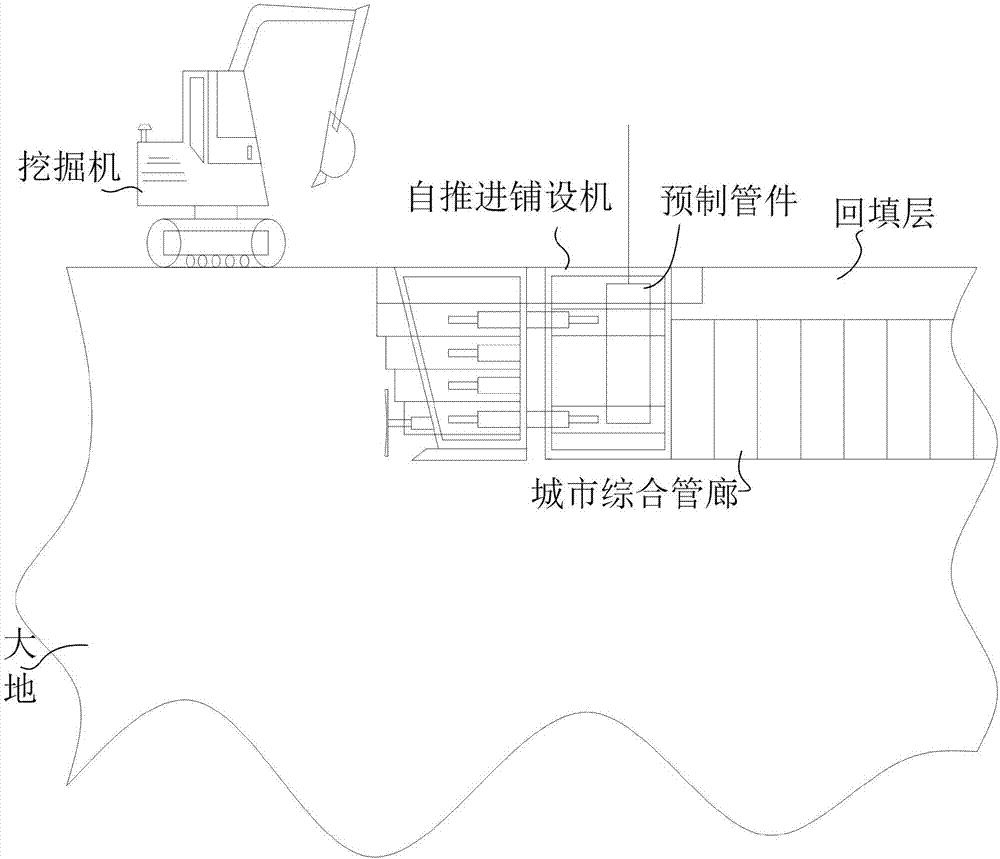
[0032] Example 1, such as figure 1 As shown, this embodiment provides an urban comprehensive prefabricated pipe corridor open-cut self-protection construction method. Specifically, this embodiment describes in detail that the width of the prefabricated pipe fittings is 2.7m and the laying depth is 8m.

[0033] First of all, here is a detailed description of the traditional process. In the traditional construction for this type of work, the width of the ground that needs to be excavated is about 13m, and the width of the lowest part is about 3.5m. Then, use the gantry crane to place the prefabricated pipe fittings into the excavated open ditch, and then the workers adjust the corresponding position to ensure that there is no deviation, then fix them, and then backfill, due to the backfill process on both sides of the prefabricated pipe fittings , cannot be compacted with a road roller, so a little bit of manual compaction is required. Due to the limited degree of manual compact...

Embodiment 2

[0041] Embodiment 2, this embodiment provides a self-propelled laying machine, and its utility model patent was applied for on the same day under the name of self-protection self-propelled laying machine for urban comprehensive pipe gallery.

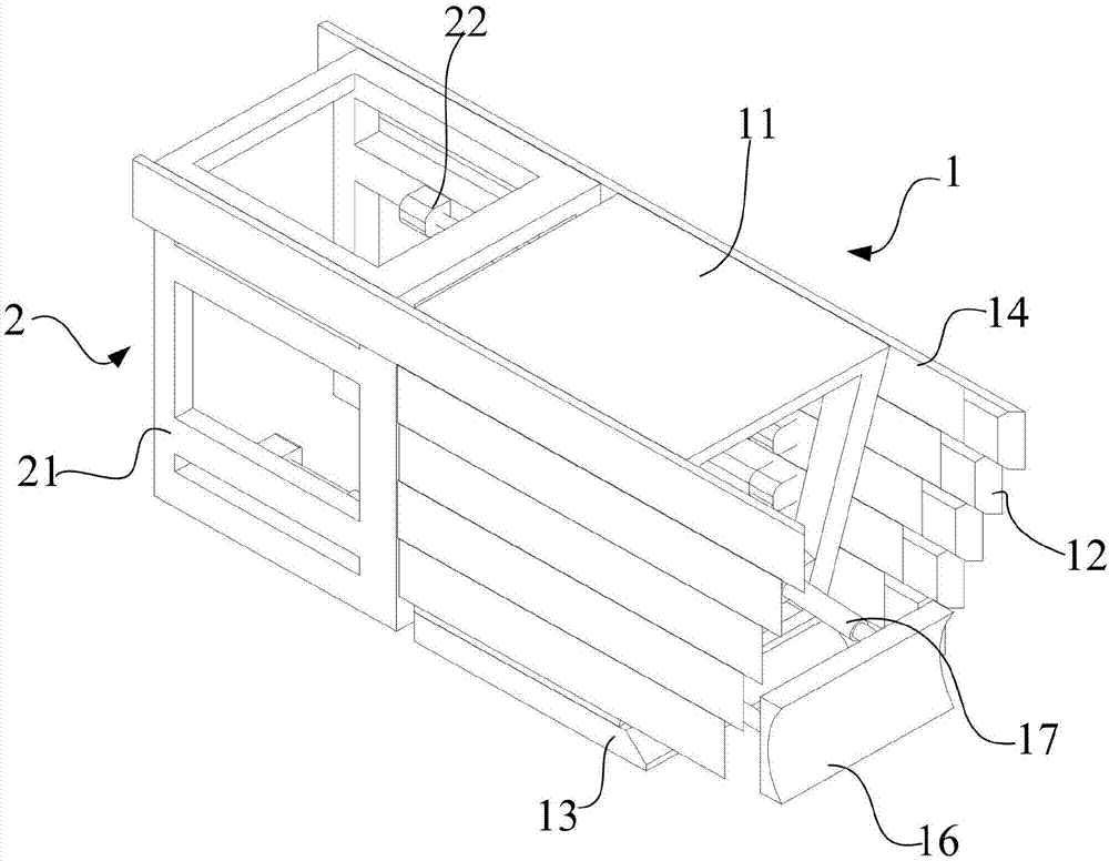
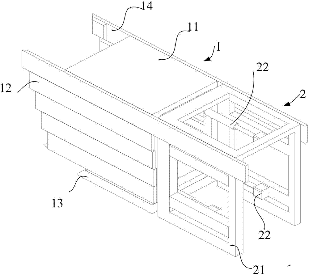
[0042] Such as figure 2 , image 3 , Figure 4 As shown, the present embodiment provides a self-propelled paver, including a shoveling part 1 and a laying part 2 connected to each other. Part 2 is mainly used for laying prefabricated pipe fittings to achieve the purpose of urban comprehensive pipe gallery construction. It should be noted here that the structure provided in this embodiment is limited to the laying of urban comprehensive pipe gallery with an excavation depth below 8m.

[0043] In order to achieve the above purpose, in this embodiment, the provided shoveling section 1 includes a frame-shaped shoveling section body 11 and shoveling boards 12 arranged on both sides of the shoveling section body 11. The whole body 11 of th...


PUM


Abstract

The invention relates to an open-cut type self-protective construction method of a city comprehensive prefabricated pipe rack and a self-propelling laying machine. The open-cut type self-protective construction method comprises the following effective methods that (a), a device assembling working face is built at the front end of a construction route firstly; (b), the self-propelling laying machine is installed on a device assembling working face site; (c), after the self-propelling laying machine is installed, an open trench with the width and the depth being slightly smaller than the width of the pipe rack needed to be laid is excavated through an excavator; (d), the width and the depth which are needed for pipe rack laying are excavated through the self-propelling laying machine; (e), after the self-propelling laying machine completes excavating, soil slag excavated through the self-propelling laying machine is excavated through the excavator, and meanwhile prefabricated pipe fittings are lifted through a lifting machine, stored into the self-propelling laying machine and well fixed; (f), after the self-propelling laying machine is driven to move according to the construction route, the prefabricated pipe fittings which are laid just now are backfilled through the excavator; and (g), motion from the step (c) to the step (g) is repeated till a device assembling working face at the other end of the construction route is built, and namely, building of the whole city comprehensive prefabricated pipe rack is completed.

Description

technical field [0001] The invention belongs to the field of urban comprehensive pipe gallery construction, and in particular relates to an urban comprehensive prefabricated pipe gallery open-cut self-protection construction method and a self-propelled laying machine. Background technique [0002] The urban pipe corridor refers to the "comprehensive corridor of municipal pipelines underground in the city", that is, a tunnel space is built underground in the city, and various pipelines such as electricity, communication, gas, water supply, heat, and drainage are intensively laid in the tunnel space, and There are special personnel entrances and exits, pipeline entrances and exits, inspection ports, hoisting ports, and disaster prevention monitoring and monitoring systems, forming a new type of comprehensive municipal public pipeline facility, and implementing unified planning, design, construction and management. [0003] At present, the main construction method of pipe corri...

Claims


Application Information

Patent Timeline
Patent Type & Authority Applications(China)
IPC IPC(8): E02D29/045E02D29/00
CPCE02D29/045E02D29/10
Inventor 曾庆如曾庆振
Owner 曾庆如
Why Eureka
Try Eureka