Support system of steam turbine generator unit

A technology for steam turbine generator sets and generator sets, which is applied to engine components, machines/engines, mechanical equipment, etc., and can solve problems such as large engineering investment, inability to solve expansion and stress problems, and inability to greatly reduce high temperature and high pressure steam pipeline straight pipes, etc. , to achieve the effect of saving investment, reducing pressure loss and reducing usage

Pending Publication Date: 2017-06-20
冯煜珵
View PDF2 Cites 10 Cited by
  • Summary
  • Abstract
  • Description
  • Claims
  • Application Information

AI Technical Summary

Problems solved by technology

Obviously, this conventional piping system connection method fails to take advantage of the high-level and low-level layout. Compared with the conventional steam turbine generator set layout, it cannot greatly reduce the straight pipes of high-temperature and high-pressure steam pipelines, and the elbows of the system are also There will still be more, so the pressure drop of the high-temperature and high-pressure steam pipeline has not dropped significantly, the economics of unit operation have not changed much, and the project investment is still large.
On the other hand, the support system of conventional low-level steam turbine generator sets usually adopts a self-supporting concrete frame structure of reinforced concrete platform and supporting columns. The impact of unit operation on the vibration of the entire supporting platform, the Chinese patent "Supporting Platform System for High-position Turbo-generator Sets" (Patent No.: ZL201120011877.2) provides a support platform system for high-position turbo-generator sets, its main principle The vibration isolation system is placed under the platform supporting the steam turbine generator set, which can solve the thermal displacement of the system in the vertical direction and alleviate the vibration impact during the operation of the high-position steam turbine generator set. However, this cannot solve the problem of the piping system between the furnaces. Expansion and stress problems in the horizontal direction caused by direct short-distance connections

Method used


Image

  • Support system of steam turbine generator unit
  • Support system of steam turbine generator unit
  • Support system of steam turbine generator unit

Examples


Embodiment 1

[0028] Such as Figure 4 As shown, it is a schematic diagram of a specific embodiment 1 of a support system of a turbogenerator set of the present invention. Among them, the boiler adopts a tower furnace, and the high-level steam turbine and the boiler (viewed from the right side of the furnace to the left side of the furnace) are arranged in parallel in the horizontal direction.

[0029] The high-level steam turbine in this embodiment adopts the support system of the present invention, mainly including support system 1, high-level steam turbine 2, outlet header 3 of the final reheater, outlet header 4 of the final superheater, high-pressure cylinder 5 and medium-pressure cylinder 6 , Hot re-steam pipes 3' and 3'', main steam pipes 4' and 4''.

[0030] Among them, the outlet header 3 of the final stage reheater and the outlet header 4 of the final superheater are all attached to the high-level steam turbine 1. Since the support system 1 adopts the support system of the present...

Embodiment 2

[0034] Such as Figure 5 As shown, it is a schematic diagram of Embodiment 2 of a support system of a turbogenerator set of the present invention. Among them, the boiler adopts a tower furnace, and the high-level steam turbine and boiler (viewed from the right side of the furnace to the left side of the furnace) are arranged vertically in the horizontal direction.

[0035]The high-level steam turbine in this embodiment adopts the support system of the present invention, mainly including support system 1, high-level steam turbine 2, outlet header 3 of the final reheater, outlet header 4 of the final superheater, high-pressure cylinder 5 and medium-pressure cylinder 6 , Hot re-steam pipes 3' and 3'', main steam pipes 4' and 4''.

[0036] Among them, the outlet header 3 of the final stage reheater and the outlet header 4 of the final superheater are all attached to the high-level steam turbine 1. Since the support system 1 adopts the support system of the present invention, that...


PUM


Abstract

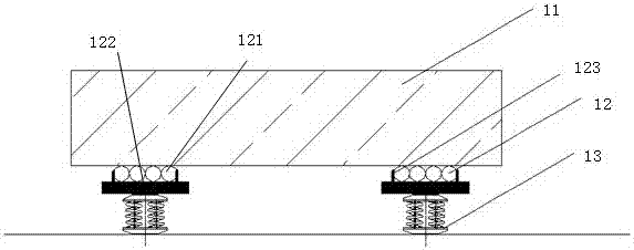
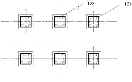
The invention discloses a support system of a steam turbine generator unit. The support system at least comprises a bedplate and a support seat, wherein the bedplate and the support seat are used for supporting the steam turbine generator unit, the support seat comprises a vibration isolation unit and a sliding unit which is located above the vibration isolation unit, the sliding unit comprises a sliding body bracket and a sliding body which is located on the bracket, the bedplate of the steam turbine generator unit is directly put on the sliding body, the sliding body bracket comprises a bottom plate and a side baffle which is perpendicular to the bottom plate and forms a sealed shape in a horizontal direction, the sliding body is located in the side baffle, and the vertical height of the sliding body is larger than the side baffle. The support system can bear the load of the steam turbine generator unit and absorb the vibration of the steam turbine generator unit and can also absorb thermal displacement in horizontal directions (X,Y) and a vertical direction (Z), the problems of thermal expansion and stress of a pipeline system for connecting a boiler with the steam turbine generator unit are solved, and the short-distance connection of the pipeline system between the boiler and the steam turbine generator unit is realized.

Description

technical field [0001] The invention relates to a supporting system of a steam turbine generator set, which belongs to the technical field of power generation. Background technique [0002] In order to realize the compact layout of the furnace and shorten the high-temperature and high-pressure steam pipes between the furnaces, the Chinese patent "A High and Low Position Split Shaft Arrangement Turbogenerator Set" (Patent No.: ZL 200710040128.0) provides a new type of steam turbine power generation Compared with the arrangement of conventional steam turbine generator sets, the layout method of the unit is to arrange the high-level and low-level shafting staggeredly, so that the high-level shafting is as close as possible to the boiler header, so that the boiler header (such as the final superheater of the boiler, The straight-line distance between the final primary reheater or the outlet header of the final secondary reheater, etc.) and the steam turbine is greatly shortened,...

Claims


Application Information

Patent Timeline
Patent Type & Authority Applications(China)
IPC IPC(8): F01D25/28F01D15/10F01D25/04
CPCF01D15/10F01D25/04F01D25/28
Inventor 冯煜珵
Owner 冯煜珵
Why Eureka
Try Eureka