
Online non-contact thickness measuring equipment and method

A non-contact, equipment technology, applied in the direction of electric/magnetic thickness measurement, measuring device, electromagnetic measuring device, etc., can solve the problems of material surface damage, measurement error, troublesome operation, etc., and achieve easy implementation, avoid damage, and simple overall structure Effect

Active Publication Date: 2017-06-20
广东嘉仪仪器集团有限公司 +1
View PDF6 Cites 8 Cited by
  • Summary
  • Abstract
  • Description
  • Claims
  • Application Information

AI Technical Summary

Problems solved by technology

[0003] However, in the production process, it is necessary to detect the thickness of non-magnetic thin-film materials; some directly use hand-held gauges or calipers to detect the thickness of non-magnetic thin-film materials after shutdown, which is cumbersome to operate and low in efficiency. Measurement is easy to cause damage to the surface of the material; some use laser triangulation, the thickness measurement module is composed of two laser displacement sensors that shoot up and down, and the upper and lower sensors respectively measure the position of the upper surface of the measured object and the position of the lower surface, the thickness of the measured object is obtained by calculation. Since the measured sheet is not an absolute plane, when the laser is reflected from a non-plane, it will cause a measurement error, and the minimum laser spot is 2 μm, so the measurement error is the least Greater than 2μm

Method used


Image

  • Online non-contact thickness measuring equipment and method
  • Online non-contact thickness measuring equipment and method
  • Online non-contact thickness measuring equipment and method

Examples


Embodiment Construction

[0030] In order to facilitate the understanding of those skilled in the art, the present invention will be further described below in conjunction with the embodiments and accompanying drawings, and the contents mentioned in the embodiments are not intended to limit the present invention. The present invention will be described in detail below in conjunction with the accompanying drawings.

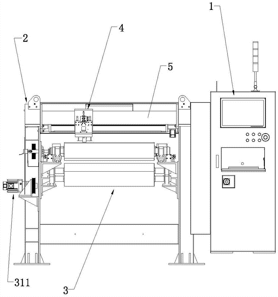
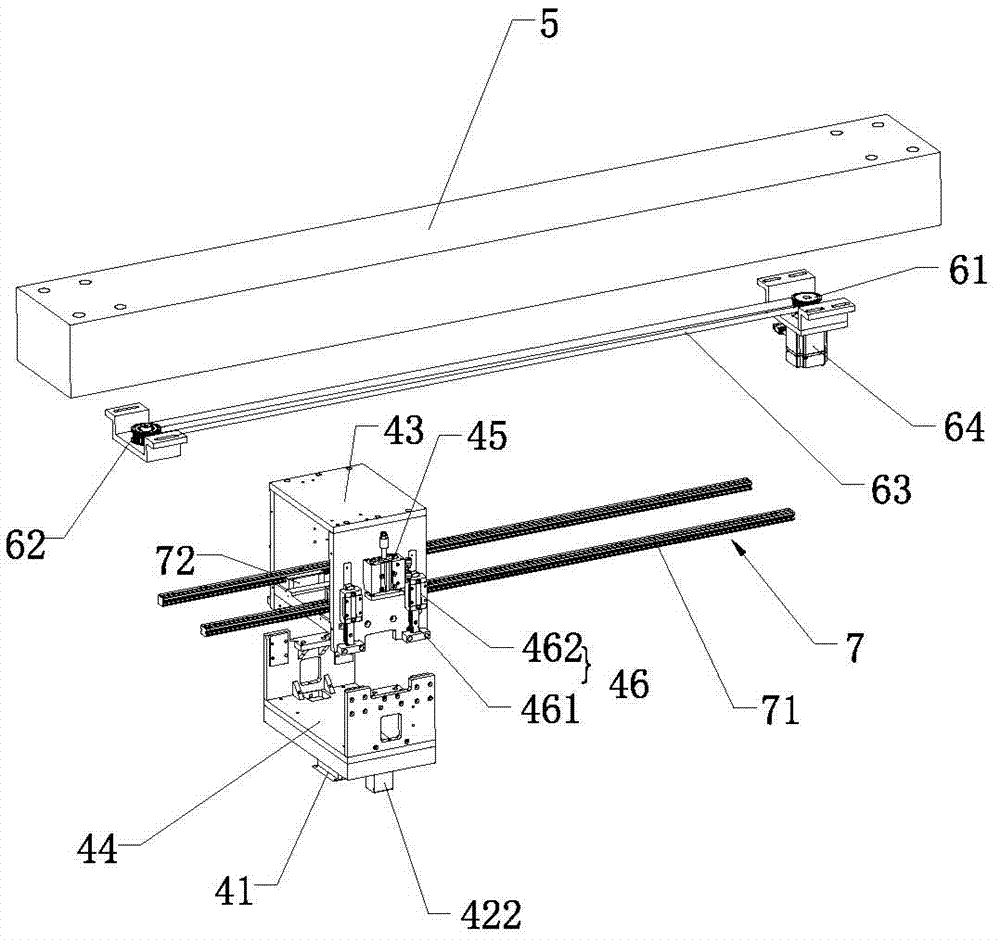
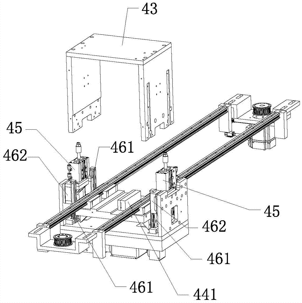
[0031] Such as figure 1 As shown, an online non-contact thickness measuring device provided by the present invention includes a center console 1 and an equipment frame 2 arranged on the side of the center console 1, and the equipment frame 2 is provided with a material guide assembly 3, a measuring Component 4 and the crossbeam top block 5 for supporting the measurement assembly 4, the measurement assembly 4 is slidably arranged on the crossbeam top block 5, the measurement assembly 4 includes a magnetic field sensor 41, a light emitter 421 and a CCD sensor 422; the guide The material asse...


PUM


Abstract

The invention relates to the technical field of detection, specifically online non-contact thickness measuring equipment. The equipment comprises a central control platform and an equipment rack disposed beside the central control platform. The equipment rack is provided with a material guide assembly, a measurement assembly, and a cross beam top block for supporting the measurement assembly. The measurement assembly is slidingly disposed on the cross beam top block, and comprises a magnetic field sensor, a light emitter and a CCD sensor. The material guide assembly comprises a driving roller and a driven roller, which are disposed below the measurement assembly. The magnetic field sensor is disposed exactly above the driving roller. The light emitter and the CCD sensor are respectively located at two sides of the driving roller, and face a position where the magnetic field sensor is aligned with the driving roller. The equipment can effectively reduce the impact on measurement from external factors through the combination of the magnetic field sensor and an optical micrometer, and can carry out the high-precision measurement of a larger area non-magnetic film.

Description

technical field [0001] The invention relates to the technical field of detection of non-magnetic thin film materials such as lithium battery pole pieces, copper foil, and aluminum foil, in particular to an online non-contact thickness measuring device and a measuring method thereof. Background technique [0002] With the deepening of production, life and scientific practice in human society, the application of non-magnetic film materials such as lithium battery pole piece, copper foil, aluminum foil is more and more widely, and has become One of the indispensable key materials in industries such as aerospace. For the produced non-magnetic thin-film materials, among its many performance requirements, the thickness and uniformity of non-magnetic thin-film materials are the most critical parameters, which directly affect the production cost and application effect, and also affect many other issues. Therefore, , Monitoring and controlling the thickness and uniformity of the fil...

Claims


Application Information

Patent Timeline
IPC IPC(8): G01B7/02G01B7/06G01B11/06
CPCG01B7/023G01B7/10G01B11/06
Inventor 郑长文
Owner 广东嘉仪仪器集团有限公司
Learn More