Closed loop fiber-optical gyroscope temperature compensating method

A technology of fiber optic gyroscope and temperature compensation, applied in the fields of inertial navigation and fiber optic sensing, which can solve the problems of high temperature signal noise, low temperature resolution, and large space required, and achieve high reliability, simple implementation method, and low cost Effect

Active Publication Date: 2017-06-20
XIAN FLIGHT SELF CONTROL INST OF AVIC
View PDF5 Cites 8 Cited by
  • Summary
  • Abstract
  • Description
  • Claims
  • Application Information

AI Technical Summary

Problems solved by technology

[0005] The purpose of the present invention is: in order to overcome the problems of complex circuit, low temperature resolution, large temperature signal noise, high cost and large space required in the existing optical fiber gyroscope temperature compensation technology, the present invention utilizes the necessary integration of...

Method used


Image

  • Closed loop fiber-optical gyroscope temperature compensating method
  • Closed loop fiber-optical gyroscope temperature compensating method
  • Closed loop fiber-optical gyroscope temperature compensating method

Examples


Embodiment

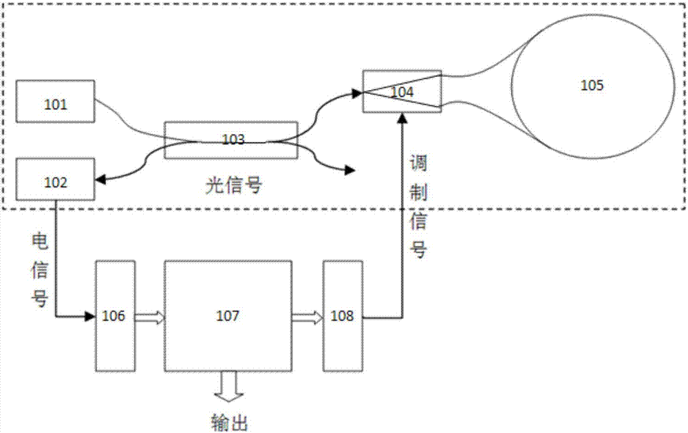
[0089] 1) Press figure 1 For the structure shown in the figure, select a loop length of 1200 meters and a closed-loop fiber optic gyroscope with a normal temperature accuracy of 0.007° / h to perform a zero-bias test with variable temperature before compensation (temperature range -40°C to +60°C, temperature change rate 1°C / min). Gyro pre-compensation output such as Figure 7 As shown, the solid line is the zero offset data, and the dotted line is the Y waveguide half-wave voltage code value data;

[0090] 2) According to the zero offset and half-wave voltage data output by the gyro, determine the gyro compensation model coefficient b by the least square method 0 、k 1 、k 2 value, calculated b 0 =8.4752,k 1 =0.0043,k 2 =0.2046, the established compensation model is:

[0091] B(v)=8.4752+0.0043v+0.2046v'

[0092] According to the compensation model, the gyroscope is compensated, and the compensation result is as follows: Figure 8 shown by the dotted line;

[0093] 3...


PUM


Abstract

The invention belongs to the technical fields of optical fiber sensing and inertial navigation, and relates to a closed loop fiber-optical gyroscope temperature compensating method. The closed loop fiber-optical gyroscope temperature compensating method is characterized in that a Y waveguide half-wave voltage substitutes temperature information to carry out temperature compensation on a closed loop fiber-optical gyroscope by using the approximate linear relationship between the Y waveguide half-wave voltage change and the temperature change of the closed loop fiber-optical gyroscope, and a four state modulation-based double-loop closed loop fiber-optical gyroscope is used to extract the change information of the waveguide half-wave voltage with the temperature in real time in order to realize the temperature sensor-free closed loop fiber-optical gyroscope temperature compensation. The method simplifies the design of software and hardware of a circuit, further reduces the size of the gyroscope, increases the compensation precision, has the characteristics of simple realization method, low cost and high reliability, and is of great significance to increase the temperature change precision of the fiber-optical gyroscope and further expand the application field of the fiber-optical gyroscope.

Description

technical field [0001] The invention belongs to the technical field of optical fiber sensing and inertial navigation, and relates to a closed-loop optical fiber gyroscope temperature compensation method, in particular to a temperature compensation method for a closed-loop optical fiber gyroscope without a temperature sensor. Background technique [0002] Fiber Optic Gyroscope (FOG for short) is an all-solid-state inertial instrument that uses the optical Sagnac effect (Sagnac) to measure the angular rate of the carrier space. With the continuous expansion of fiber optic gyroscope technology and its application fields, the requirements for the accuracy of fiber optic gyroscopes in variable temperature environments are constantly increasing. [0003] At present, the accuracy degradation of fiber optic gyroscopes in variable temperature environments has always been one of the important factors that affect the further improvement of fiber optic gyroscope performance and the expa...

Claims


Application Information

Patent Timeline
IPC IPC(8): G01C25/00
CPCG01C25/005
Inventor 谷林梁霄李彬
Owner XIAN FLIGHT SELF CONTROL INST OF AVIC
Why Eureka
Try Eureka