
Optical lens, optical range finding device, optical range finding method and range finding system

An optical distance measurement and lens technology, which is applied in measuring devices, radio wave measurement systems, electromagnetic wave reradiation, etc., can solve problems such as fluctuations in distance measurement results, inaccurate distance measurement of obstacles, and failure to detect them

Inactive Publication Date: 2017-06-20
BENEWAKE BEIJING TECH CO LTD
View PDF6 Cites 11 Cited by
  • Summary
  • Abstract
  • Description
  • Claims
  • Application Information

AI Technical Summary

Problems solved by technology

In the triangulation ranging method using a laser light source or the time-of-flight method using a single-point light source, when detecting complex objects, such as grass and other objects, due to the high collimation of the laser light source or single-point light source, it is used for low-altitude aircraft detection. When the height between itself and the ground is high, the ranging results will fluctuate greatly
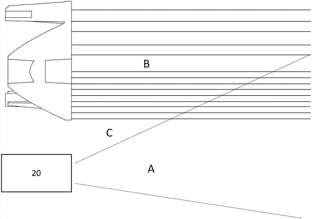
[0003] In addition, in the existing optical ranging method, the emitted probe light beam is usually not on the same optical axis as the return beam received by the receiving device, and the emitted probe light beam is usually a nearly collimated beam. Such a structure When the distance between the obstacle and the distance measuring device is very close, the obstacle in the field of view of the receiving device cannot be irradiated by the detection beam, and there will be a detection blind area, so that the distance measuring device can measure the distance of the obstacle in the short distance inaccurate or undetectable

Method used


Image

  • Optical lens, optical range finding device, optical range finding method and range finding system
  • Optical lens, optical range finding device, optical range finding method and range finding system
  • Optical lens, optical range finding device, optical range finding method and range finding system

Examples


Embodiment Construction

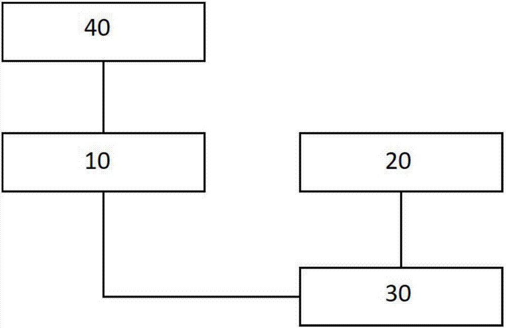
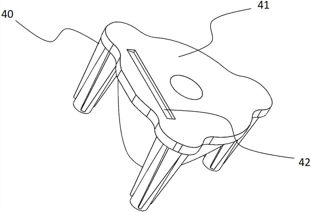
[0032] This application provides a small optical distance measuring device, as attached figure 1 As shown, it includes an infrared light emitting module 10 , a receiving module 20 , and a signal processing and control module 30 . Wherein, the signal processing and control module 30 is connected with the infrared light emitting module 10 and the receiving module 20 respectively. In one of the embodiments, a TIR lens 40 is further arranged on the optical path of the infrared detection light emitted by the infrared light emitting module.

[0033] When the small optical distance measuring device receives the work order, the signal processing and control module 30 sends a modulation signal to the infrared light emitting module 10, and the infrared light emitting module 10 emits infrared detection light modulated by the modulation signal, and the infrared detection light is emitted to the outside environment to be detected. The infrared detection light is reflected when it encount...


PUM


Abstract

In order to solve a problem of a detection blind region in a range finding device of a non-coaxial optical structure, the invention discloses a small optical range finding device, a range finding method, a range finding system and a TIR lens. The small optical range finding device comprises an infrared light emitting module, a receiving module and a signal processing and controlling module. The signal processing and controlling module is connected with the infrared light emitting module and the receiving module. The infrared light emitting module emits infrared detection light which is reflected when meeting an object. The receiving module receives infrared detection light reflected by the object, and converts optical signals into electric signals. The signal processing and controlling signal calculates the distance between the small optical range finding device and the object based on a flight time method. The TIR lens equipped with a light guiding structure is arranged on an infrared detection optical path given out by the infrared light emitting module. The light guiding structure is a groove which is arranged in a position, near one side of the receiving module, of a light emitting face the TIR lens.

Description

technical field [0001] The present application relates to a small optical distance measuring device, in particular to a small optical distance measuring device based on Time of Flight (TOF for short), an optical lens, and a distance measuring system. Background technique [0002] In the prior art, the most common optical ranging method is the triangular ranging method, which mainly uses a laser light source to emit detection light. In the triangulation ranging method using a laser light source or the time-of-flight method using a single-point light source, when detecting complex objects, such as grass and other objects, due to the high collimation of the laser light source or single-point light source, it is used for low-altitude aircraft detection. When the height between itself and the ground is high, the ranging results will fluctuate greatly. [0003] In addition, in the existing optical ranging method, the emitted probe light beam is usually not on the same optical axi...

Claims


Application Information

Patent Timeline
IPC IPC(8): G01S7/481G01S17/08
CPCG01S7/481G01S17/08
Inventor 王瑞郑凯李远
Owner BENEWAKE BEIJING TECH CO LTD
Learn More