Vibration event mode identification method

A pattern recognition and event technology, applied in the field of pattern recognition, can solve the problems of large limitations, single vibration event, low recognition rate of intrusion behavior, etc., and achieve the effect of accurate segmentation

Active Publication Date: 2017-06-20
CSIC NO 710 RES & DEV INST
View PDF9 Cites 30 Cited by
  • Summary
  • Abstract
  • Description
  • Claims
  • Application Information

AI Technical Summary

Problems solved by technology

However, at present, commercial perimeter intrusion warning systems have appeared at home and abroad, and most of them can only be used to locate the location of possible abnormal events. The method used to identify intrusion behavior is usually to analyze the time domain and frequency domain of the vibration signal, but this method It is somewhat singl

Method used


Image

  • Vibration event mode identification method
  • Vibration event mode identification method
  • Vibration event mode identification method

Examples


Example Embodiment

[0043] Example 1,

[0044] The pattern recognition method of this vibration event is realized as follows:

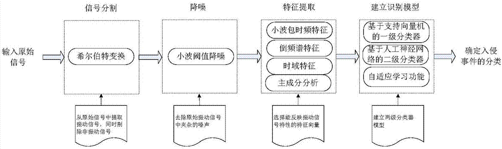
[0045] A pattern recognition method for vibration events, the basic implementation process is as figure 1 Shown:

[0046] Step 1: Segmentation of vibration and non-vibration signals in the original signal

[0047] When no vibration event occurs, the original signal collected by the vibration sensor does not contain vibration information. When a vibration event occurs, a piece of the collected original signal will contain a vibration signal and a non-vibration signal, the two appear alternately, and only the vibration signal is useful information. Therefore, splitting the vibration signal from the original signal and only letting the vibration signal enter the subsequent processing can greatly reduce system resource consumption and improve system real-time performance. In the present invention, the Hilbert transform seeking envelope principle is used to enhance the vibration s...

Example Embodiment

[0058] Examples,

[0059] 1) Signal segmentation

[0060] The original signal f(t) segmentation is to extract the real vibration segment from a segment of the original signal as the subsequent processing object. There are three points to pay attention to when extracting the vibration part of the signal: one is to segment the vibration signal segment, otherwise it will cause the system to miss the report; the second is to segment the complete, otherwise the signal information will be lost, which will affect the subsequent recognition; the third is not to divide the non-vibration The signal is divided as a vibration signal, otherwise the system will cause a false alarm.

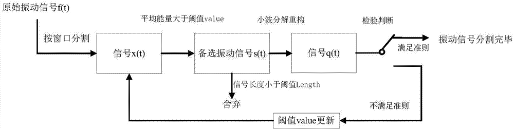
[0061] For signal segmentation, the following introduces the adaptive segmentation algorithm used in the present invention. figure 2 The flow chart of the adaptive segmentation algorithm, the detailed steps are as follows:

[0062] Step 101: Preset the vibration signal standard, and perform a preliminary analysis on ...


PUM


Abstract

The invention discloses a vibration event mode identification method. The method includes acquiring and obtaining the original vibration signals, including the vibration signal and the non-vibration signal, via a vibration sensor; separating the vibration signal in the original vibration signals; denoising the vibration signal; performing feature extraction on the denoised vibration signal and obtaining the characteristic vector including three characteristics of: A performing wavelet packet decomposition on the time-frequency domain and obtaining the energy characteristic vector, B performing the cepstrum analysis and extracting the cepstrum parameter characteristics, and C extracting the signal characteristic on the time domain; and establishing an identification model composed of two grades of classifiers, wherein the first grade of classifier is a classifier based on SVM and divides the vibration events into non-intrusive events and intrusion events by taking the characteristic vector extracted from the vibration signal as the input, and the second grade of classifier performs the identification based on the artificial nerve network for the intrusion events to obtain the classification result.

Description

technical field [0001] The invention relates to the field of pattern recognition, in particular to a method for pattern recognition of vibration events. Background technique [0002] Vibration sensors are everywhere along national borders, railways, industrial pipelines, important places, and residential quarters, and have been widely used in security monitoring and other fields. For example, in the defense along the railway line, potential safety hazards can be found, so that the staff can prevent them in advance; another example is the perimeter defense, which can be used in places such as homes, schools, residences, important institutions, financial centers, etc., to detect external intrusions immediately; in addition, Vibration sensors have also found important applications in earthquake and tsunami detection. However, at present, commercial perimeter intrusion warning systems have appeared at home and abroad, and most of them can only be used to locate the location of ...

Claims


Application Information

Patent Timeline
IPC IPC(8): G06K9/00G06N3/08
CPCG06N3/08G06F2218/04G06F2218/08G06F2218/12
Inventor 孙诚赵卓张吟李莉寿丽莉
Owner CSIC NO 710 RES & DEV INST
Why Eureka
Try Eureka