
Miniaturized wideband frequency-directional diagram reconfigurable antenna

A technology for reconfiguring antennas and directional diagrams, applied to antennas, slot antennas, electrical components, etc., can solve the problems of large number of antennas in wireless communication systems, poor performance of reconfigurable antennas, and large equipment volume, and achieve simple antenna structure, Low cost, the effect of achieving broadband performance

Inactive Publication Date: 2017-06-20
SHANXI UNIV
View PDF5 Cites 8 Cited by
  • Summary
  • Abstract
  • Description
  • Claims
  • Application Information

AI Technical Summary

Problems solved by technology

[0005] The purpose of the present invention is to solve the technical problems of large number of antennas, large equipment volume, and low integration in the current wireless communication system, and further solve the problems of poor performance and complex structure of the existing frequency-pattern reconfigurable antennas, and provide a miniaturized broadband frequency - Pattern reconfigurable antenna

Method used


Image

  • Miniaturized wideband frequency-directional diagram reconfigurable antenna
  • Miniaturized wideband frequency-directional diagram reconfigurable antenna
  • Miniaturized wideband frequency-directional diagram reconfigurable antenna

Examples


Embodiment Construction

[0033] In order to make the purpose, technical solution and advantages of the present invention clearer, the following will further describe the implementation of the present invention in detail in conjunction with the accompanying drawings.

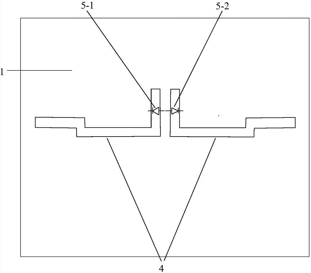
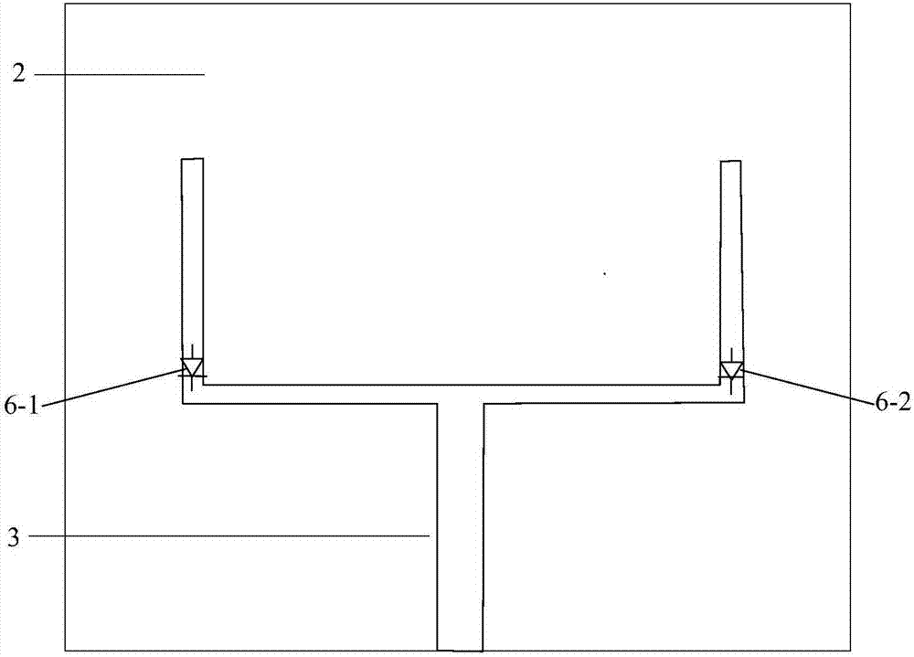
[0034] Such as figure 1 with figure 2 As shown, a miniaturized broadband frequency-pattern reconfigurable antenna in this embodiment includes a ground plate 1, a dielectric substrate 2, a fork microstrip feeder 3 and 4 PIN diodes 5-1, 5-2, 6-1, 6-2, two sickle-shaped gaps 4 are symmetrically arranged on the left and right sides of the ground plate 1, the ground plate 1 is arranged on the upper surface of the dielectric substrate 2, and the first PIN diode 5-1 and the second PIN diode 5-2 are respectively loaded on the vertical slots of the two sickle-shaped slots 4, and are disconnected or turned on at the same time; the fork-shaped microstrip feeder 3 is arranged on the lower surface of the dielectric substrate 2, and the U of the for...


PUM

PropertyMeasurementUnit
Sizeaaaaaaaaaa
Thicknessaaaaaaaaaa
Characteristic impedanceaaaaaaaaaa

Abstract

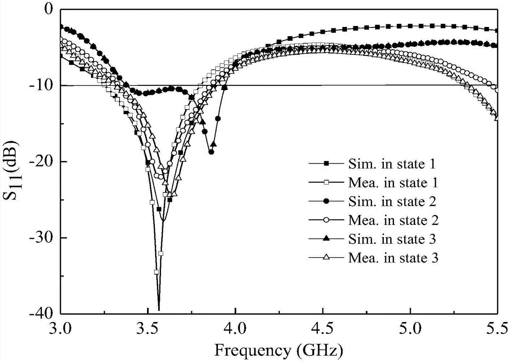
The invention relates to a miniaturized wideband frequency-directional diagram reconfigurable antenna. With the miniaturized wideband frequency-directional diagram reconfigurable antenna, technical problems of many antennas and low radio-frequency front-end integration degree of the existing wireless communication system can be solved. The reconfigurable antenna comprises a ground plate, a dielectric substrate, a forked microstrip feeder and four PIN diodes. The ground plate is arranged at the upper surface of the dielectric substrate; the first PIN diode and the second PIN diode are loaded on a vertical gap between two sickle type gaps of the ground plate and are connected or disconnected simultaneously; the forked microstrip feeder is arranged at the lower surface of the dielectric substrate; and the third PIN diode and the fourth PIN diode are loaded at connection part of a horizontal branch and a vertical branch of a U-shaped structure of the forked microstrip feeder respectively and are connected simultaneously or one of the third PIN diode and the fourth PIN diode is connected. With control of different combination states of the diodes, the antenna realization frequency and the directional diagram can be reconstructed. The antenna that can work at the frequency band of a fourth generation mobile communication system TD-LTE (3.4-3.8GHz) and a satellite communication system C-band (3.7-4.2GHz) has advantages of simple structure, low cost, and high reliability and can meet the compact and high-integration requirement of the wireless communication system.

Description

technical field [0001] The invention belongs to the technical field of antennas in the comprehensive design of communication systems, and in particular relates to a miniaturized broadband frequency-pattern reconfigurable antenna. Background technique [0002] With the development of wireless communication systems towards large capacity and multi-function, it is imperative to improve the capacity of communication systems and the utilization of spectrum resources. As one of the important components of the wireless communication system, the research and design of the antenna is facing unprecedented challenges. While the antenna is required to be smaller and lighter, the antenna should also have multiple operating frequency bands. However, this will inevitably increase the number of components in the communication system. number of antennas. Reconfigurable antennas can change the operating frequency, radiation pattern and polarization mode of the antenna according to the requir...

Claims


Application Information

Patent Timeline
IPC IPC(8): H01Q25/04H01Q3/34H01Q13/10
Inventor 韩丽萍韩国瑞王彩霞张文梅
Owner SHANXI UNIV
Learn More