
Stability determination method for DC micro-grid in master-slave control mode

A DC microgrid and control mode technology, applied in the field of stability analysis, can solve problems such as unclear physical meaning, complex system matrix, unfavorable expansion, etc., and achieve the effects of easy expansion, wide application range, and simplified calculation

Active Publication Date: 2017-06-20
ZHEJIANG ZHONGXIN POWER ENG CONSTR CO LTD +1
View PDF1 Cites 5 Cited by
  • Summary
  • Abstract
  • Description
  • Claims
  • Application Information

AI Technical Summary

Problems solved by technology

The document "Reduced-order model and stability analysis of low-voltage DC microgrid" establishes a complete state-space model of the ring-network DC microgrid, and obtains the characteristic root of the system matrix to analyze the system stability, but requires a detailed model of each part of the system, and obtains The system matrix of is also complex, and the physical meaning corresponding to each matrix element is not clear
The document "Modeling and analysis of harmonicstability in an AC power-electronics-based power system" applies the unit connection method to the master-slave controlled AC microgrid to analyze the system stability, which has a clear physical meaning and can be measured by an impedance analyzer. The impedance and admittance of each power module are modeled, but the admittance matrix of the system node is not separated from the impedance of other parts. It is difficult to intuitively obtain the generalized stability criterion of the system, which is not conducive to expansion

Method used


Image

  • Stability determination method for DC micro-grid in master-slave control mode
  • Stability determination method for DC micro-grid in master-slave control mode
  • Stability determination method for DC micro-grid in master-slave control mode

Examples


Embodiment Construction

[0033] Below in conjunction with accompanying drawing, the present invention is described in further detail:

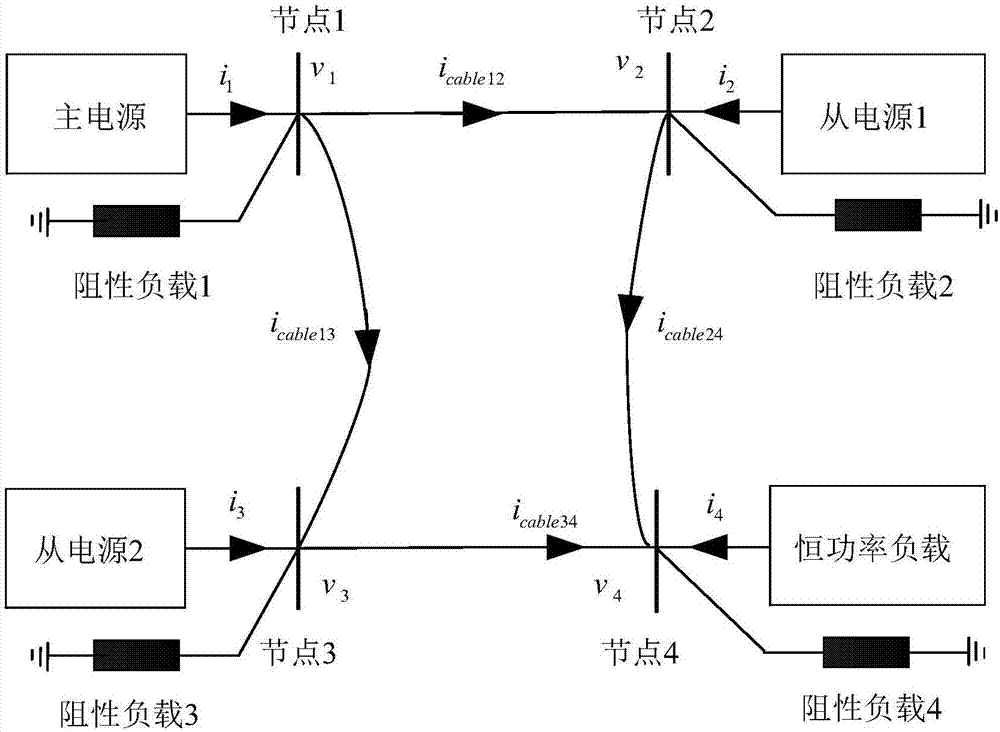
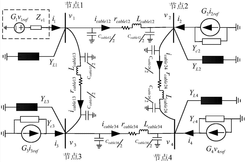
[0034] A 4-node DC microgrid considering the impedance between nodes is as follows: figure 1 shown. There is one main power supply, two slave power supplies and one constant power load in the system; the node connected to the main power supply is node 1, the two slave power supplies are connected to node 2 and node 3 respectively, and the constant power load is connected to node 4; The nodes are connected by cables. The main power supply adopts constant voltage control to maintain the system voltage at the rated point; the slave power supply adopts current control to control the current input from the power supply to the system; the constant power load absorbs constant power from the system through control. where v 1 ~v 4 is the voltage of 4 nodes; i 1 ~i 4 is the current injected by the four power modules into the node, and the flow out of the power module is i...


PUM


Abstract

The invention relates to the stability analysis technology in the DC micro-grid technologies, and aims to provide a stability determination method for a DC micro-grid in the master-slave control mode. The method comprises the following steps: using the unit connection method to carry on the Thevenin / Norton equivalent to the power modules of each power supply and each constant power load so as to obtain the corresponding impedance / admittance, and obtaining the impedance matrix of the main power supply, the admittance matrixes of the slave power source and the constant power load; according to the known resistive load size of each node, obtaining the resistive load admittance matrix, and obtaining the system node admittance matrix according to the inter-node cable parameter; placing each matrix into the stability criterion and calculating its pole; if all the poles are on the left half plane, determining that the system is stable; and if there is a pole on the right half plane, determining the system is unstable. The method is compatible with the inter-node impedance of the system, and has no specific requirement for the system structure, and has a wide application range. The calculation is simplified in the system-level stability analysis and the stability of the complex DC micro-grid can be effectively analyzed.

Description

technical field [0001] The invention relates to a method for judging the stability of a DC micro-grid under a master-slave control mode, and belongs to the stability analysis technology in the DC micro-grid technology. Background technique [0002] With the massive access of renewable new energy, DC microgrid is widely used as an efficient utilization system. A DC microgrid is generally composed of power modules such as multiple power supplies and constant power loads. Master-slave control is adopted between multiple power supplies, that is, one power supply is a voltage-controlled power supply as the main power supply, and the other power supplies are current-controlled power supplies as slave power supplies. Usually, a single power module can ensure stability when running independently during control design, but it will affect each other when forming a system, reducing system stability. On the other hand, the external characteristics of negative impedance of constant powe...

Claims


Application Information

Patent Timeline
IPC IPC(8): H02J1/10G06F17/50
CPCG06F30/20H02J1/10H02J2203/20Y02P80/14
Inventor 彭勇刚胡辉勇韦巍
Owner ZHEJIANG ZHONGXIN POWER ENG CONSTR CO LTD
Learn More