Microgrid energy storage converter control method

A technology of an energy storage converter and a control method, applied in the direction of converting AC power input into DC power output, output power conversion device, electrical components, etc., capable of solving low power factor, low grid side power factor, and DC voltage ripple To solve problems such as large waves, achieve the effects of improving tracking speed and accuracy, feasible and effective control methods, and stable DC side voltage

Inactive Publication Date: 2017-06-20
邢筱丹
View PDF0 Cites 3 Cited by
  • Summary
  • Abstract
  • Description
  • Claims
  • Application Information

AI Technical Summary

Problems solved by technology

Diode uncontrolled rectifiers and thyristor phase-controlled rectifiers have defects such as serious input current distortion, low power factor, and easy to cause electromagnetic interference, so they are gradually eliminated
Traditional PWM converters have large power switching losses, high current harmonic content, low grid-side power factor and large DC voltage ripple, so they are not suitable for micro-grid energy storage systems

Method used


Image

  • Microgrid energy storage converter control method
  • Microgrid energy storage converter control method
  • Microgrid energy storage converter control method

Examples


Embodiment Construction

[0017] specific implementation plan

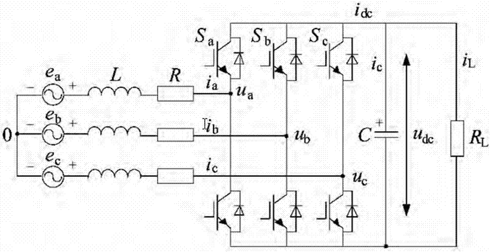
[0018] figure 1 In the figure, the phase voltage of the grid side is shown in the figure, ia\b\c is the phase current of the grid side; it is the inductance of the grid side; r\* MERGEFORMAT is the equivalent resistance of the AC side; c\* MERGEFORMAT is the capacitance of the DC side; udc is the DC side Voltage; idc is the DC side current; rl is the equivalent resistance of the DC side; il is the equivalent resistance current of the DC side. Define sj as the unipolar binary logic switching function of the converter, then sj=1, the upper bridge arm is turned on, and the lower bridge arm is turned off; sj=0, the lower bridge arm is turned on, and the upper bridge arm is turned off. where j = a, b, c.

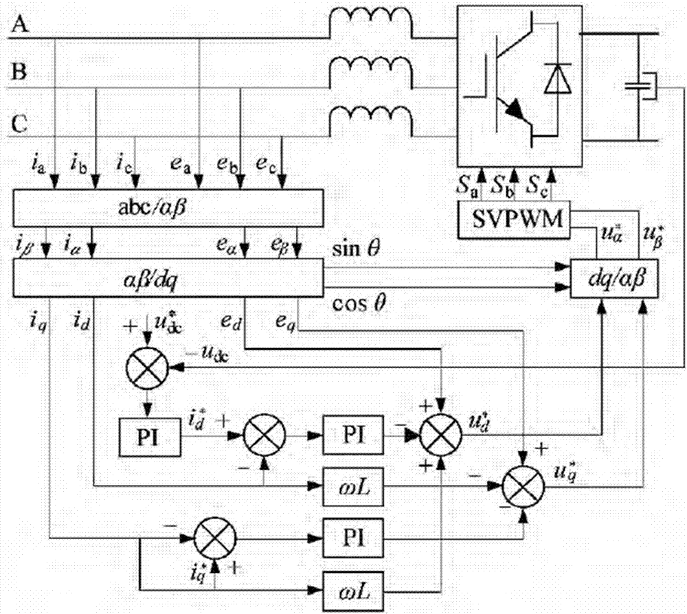
[0019] The main purpose of micro-grid energy storage converter control is to make the grid-side current sinusoidal and the DC-side voltage stable. To achieve the goal, a direct current control method based on grid voltage orientation is ado...


PUM


Abstract

The present invention discloses a microgrid energy storage converter control method. The method comprises three parts consisting of a microgrid energy storage converter, a voltage outer ring and a current inner ring. The present invention provides a grid voltage orientation double closed loop control strategy fusing feedforward decoupling control. On the basis of a three-phase voltage source converter (d, q) coordinate system mathematic model, grid voltage vector orientation and synchronous rotation are performed, the current inner ring employs the feedforward decoupling direct current control to decouple active current and reactive current so as to improve tracking speed and precision of the inner ring current and enhance the response speed of the outer ring voltage. A simulation result show that: the response speed of the converter system is fast, the grid-side current harmonic content is low, voltage at the direct current side is stable and the ripple voltage is small so that a unit power factor can be used for both-way operation. The provided control method is effective and feasible, and has an application reference value.

Description

[0001] Technical field [0002] The invention relates to a micro-grid energy storage converter, in particular to a control method for a micro-grid energy storage converter. Background technique [0003] With the development of the economy, environmental pollution and energy shortage have become serious problems faced by all countries in the world, which has led to the rapid development of renewable energy such as solar energy and wind energy. Diode uncontrolled rectifiers and thyristor phase-controlled rectifiers have defects such as serious input current distortion, low power factor, and easy to cause electromagnetic interference, so they are gradually eliminated. The PWM rectifier has the advantages of fast system dynamic response, low harmonic content, and high power factor. With the development of rectifier technology, three-level PWM rectifiers can make power devices with low withstand voltage and low operating current work in high-voltage and high-power occasions, and c...

Claims


Application Information

Patent Timeline
Patent Type & Authority Applications(China)
IPC IPC(8): H02M7/219
CPCH02M7/219H02M7/2195
Inventor 邢筱丹
Owner 邢筱丹
Why Eureka
Try Eureka