A led dimming control circuit

A technology of dimming control circuit and control chip, applied in the direction of light source, electric light source, electrical components, etc., can solve problems such as many components, and achieve the effect of solving many components

Active Publication Date: 2018-07-10
BCD (SHANGHAI) MICRO ELECTRONICS LTD
View PDF8 Cites 0 Cited by
  • Summary
  • Abstract
  • Description
  • Claims
  • Application Information

AI Technical Summary

Problems solved by technology

[0003] In view of this, the present invention provides an LED dimming control circuit to solve the problem of many components in the prior art

Method used


Image

  • A led dimming control circuit
  • A led dimming control circuit
  • A led dimming control circuit

Examples


Embodiment Construction

[0037] The following will clearly and completely describe the technical solutions in the embodiments of the present invention with reference to the accompanying drawings in the embodiments of the present invention. Obviously, the described embodiments are only some, not all, embodiments of the present invention. Based on the embodiments of the present invention, all other embodiments obtained by persons of ordinary skill in the art without making creative efforts belong to the protection scope of the present invention.

[0038] The invention provides an LED dimming control circuit to solve the problem of many components in the prior art.

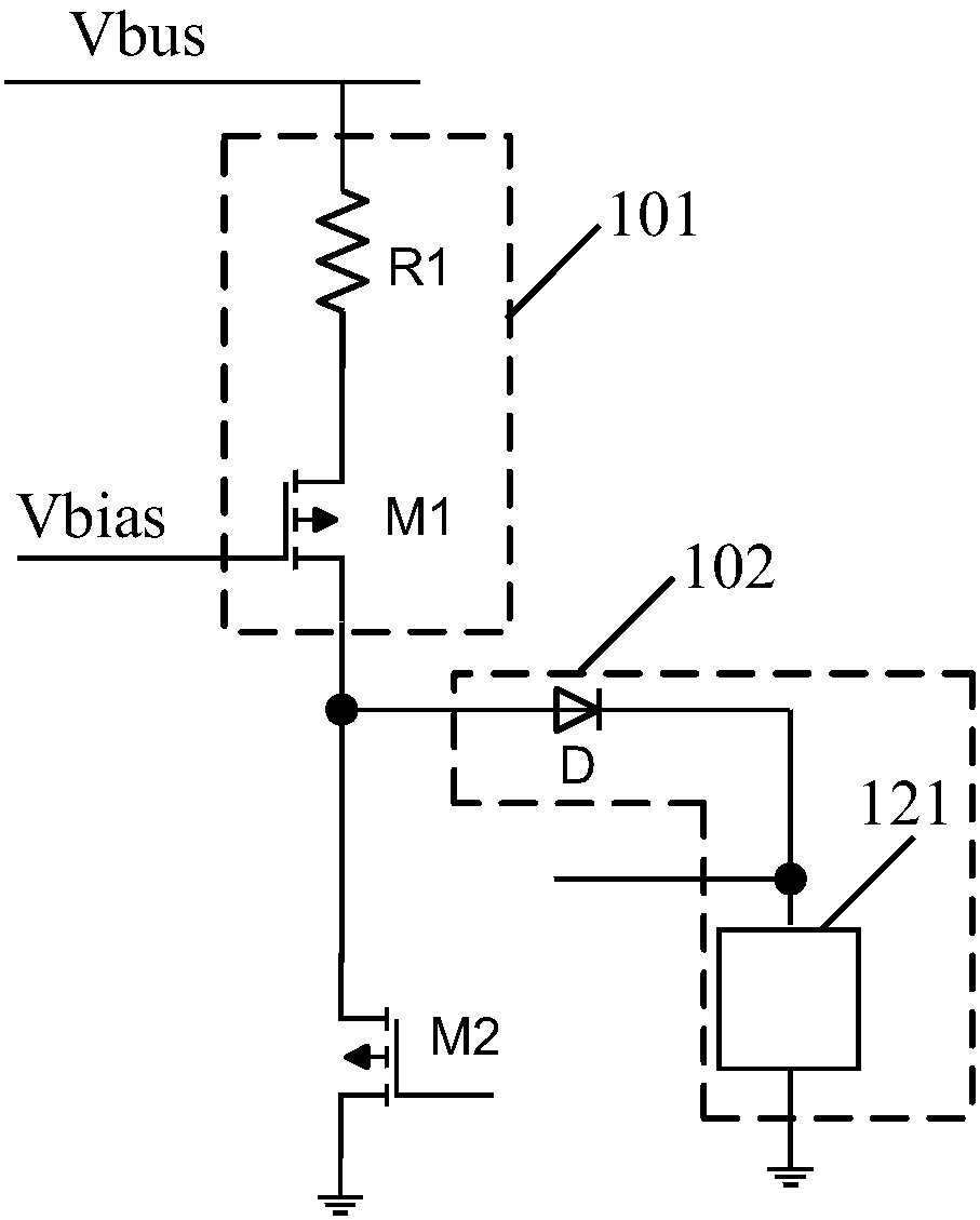
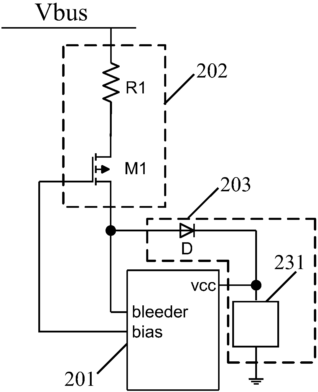
[0039] Specifically, such as figure 2 As shown, the LED dimming control circuit at least includes: a discharge module 101 and a high voltage starting module 102;

[0040] Wherein, the relief module 101 includes:

[0041] a first resistor R1 receiving line voltage at one end;

[0042] The first end of the first switching tube M1 is connec...


PUM


Abstract

This application provides an LED dimming control circuit, which forms a discharge module through the first resistor and the first switch tube, and realizes the discharge function in LED dimming control in combination with the second switch tube; a high-voltage start-up composed of a diode and an energy storage device module, combined with the output voltage of the first terminal of the second switching tube, charges the energy storage device through the diode, and provides working power for the LED dimming control circuit to realize the high-voltage starting function; compared with the prior art, this The application adopts fewer components and parts to realize the discharge function and the high-voltage starting function, and solves the problem of many components and parts in the prior art.

Description

technical field [0001] The invention relates to the technical field of LED control, in particular to an LED dimming control circuit. Background technique [0002] figure 1 Shown is a conventional LED dimming control circuit topology with bleeder function and high-voltage start-up function. Among them, the first resistor R1 and the first switch tube M1 form a module to realize the discharge function, and the second resistor R2, the third resistor R3, the first capacitor C1, the second switch tube M2, and the diode D2 form a module to realize the high-voltage start function. module; the module realizing the high-voltage starting function is connected to the power supply pin vcc of the control chip; by figure 1 It can be seen that there are many components in the conventional topology in the prior art. Contents of the invention [0003] In view of this, the present invention provides an LED dimming control circuit to solve the problem of many components in the prior art. ...

Claims


Application Information

Patent Timeline
Patent Type & Authority Patents(China)
IPC IPC(8): H05B33/08H02M1/36H05B44/00
CPCH02M1/36H05B45/37Y02B20/30
Inventor 邓超陈泽强刘娜徐思远
Owner BCD (SHANGHAI) MICRO ELECTRONICS LTD
Why Eureka
Try Eureka