Artificial shoulder joint prosthesis

A shoulder joint and prosthesis technology, applied in the field of human shoulder joint replacement, can solve the problems of multi-level porous material properties such as uneven mechanical strength and elastic modulus, failure to meet the functional requirements of bionic artificial bones, and insufficient uniformity, etc., to achieve convenience The effect of fixing the product position, good structural mechanical properties, and reducing product quality

Inactive Publication Date: 2017-06-23
CHONGQING RUNZE PHARM CO LTD
View PDF13 Cites 2 Cited by
  • Summary
  • Abstract
  • Description
  • Claims
  • Application Information

AI Technical Summary

Problems solved by technology

CN201210185031 discloses a method for preparing a bionic artificial bone with a multi-level (micron / nano) pore structure. However, the three-dimensional multi-level pore structure obtained by this method still cannot meet the bionic requirements due to the randomness and irregularity of its pore structure. Functional Requirements of Artificial Bone
[0005] In addition, as a multi-level porous material applied to bionic artificial bone, the material itself needs to be uniform, that is, the size of the pores and the distribution of the pores are uniform, so that the performance is uniform, but in fact, there are many multi-level porous materials that cannot meet this requirement. Its uniformity is insufficient; although some materials claim to have achieved high uniformity, their uniformity is still the uniformity at the large volume scale. For a three-dimensional body larger than one cubic centimeter, the mass of the three-dimensional body is measured separately, and the difference in the degree of inhomogeneity is still very large, so the various properties of the porous material such as mechanical strength, elastic modulus, etc. are inhomogeneous, which seriously affects its function.

Method used


Image

  • Artificial shoulder joint prosthesis
  • Artificial shoulder joint prosthesis
  • Artificial shoulder joint prosthesis

Examples


Embodiment 1

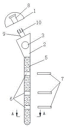
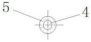
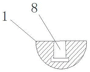
[0029] As attached to the manual Figure 1-3Shown, a kind of artificial shoulder joint prosthesis, it comprises humerus head 1 and humerus stem 2; Its humerus stem 2 upper part is provided with round hole 3, and its lower handle body is by body 4, and is located at the wrapping of body 4 outer layers The cladding layer 5 is composed of a cladding layer 5, wherein the cladding layer 5 is made of a multi-level porous material; a plurality of through holes 6 are uniformly distributed on the handle body, and nails 7 are matched in the through holes 6; the humeral head 1 is provided with Installation groove 8, and the diameter of installation groove 8 bottom is greater than the diameter of upper part; The upper end face of its humerus handle 2 is connected with fixed rod 9; Clip 10; the fixed rod 9 is inserted into the installation groove 8, the elastic clip 10 on the upper end of the fixed rod 9 fits in the lower part of the installation groove 8, and the barb hook on the elastic ...

Embodiment 2

[0040] As attached to the manual Figure 4 Shown, a kind of artificial shoulder joint prosthesis, it comprises humerus head 1 and humerus stem 2; Its humerus stem 2 upper part is provided with round hole 3, and its lower handle body is by body, and is located at the cladding layer of body outer layer 5 components, wherein, the cladding layer 5 is made of multi-level porous material; a plurality of through holes 6 are evenly distributed on the handle body; a mounting groove 8 is provided inside the humeral head 1, and the diameter of the lower part of the mounting groove 8 is larger than that of the upper part diameter; the upper end surface of the humerus stem 2 is connected with a fixed rod 9; the upper end of the fixed rod 9 is provided with two symmetrically distributed elastic clips 10 with barbs; the fixed rod 9 is inserted into the installation groove 8, The elastic clip 10 on the upper end of the fixed rod 9 fits in the lower part of the installation groove 8, and the b...

Embodiment 3

[0052] As attached to the manual Figure 5 Shown, a kind of artificial shoulder joint prosthesis, it comprises humerus head 1, humerus stem 2 and buffer pad 11; Its humerus stem 2 upper part is provided with round hole 3, and its lower handle body is by body, and is located at body outer layer The cladding layer 5 is composed of a cladding layer 5, wherein the cladding layer 5 is made of a multi-level hole material; a plurality of through holes 6 are evenly distributed on the handle body, and nails 7 are matched in the through holes 6; the inside of the humeral head 1 An installation groove 8 is provided, and the diameter of the lower part of the installation groove 8 is greater than that of the upper part; the upper end surface of the humerus handle 2 is connected with a fixed rod 9; The elastic clip 10; its fixed rod 9 passes through the buffer pad 11 and is inserted into the installation groove 8, the elastic clip 10 on the upper end of the fixed rod 9 fits in the lower par...


PUM


Abstract

The invention relates to an artificial shoulder joint prosthesis. The artificial shoulder joint prosthesis comprises a humeral head (1) and a humeral handle (2), and is characterized in that a round hole (3) is arranged at the upper part of the humeral handle (2), wherein the lower handle body of the humeral handle (2) is composed of a body (4) and a coating layer (5) arranged at the outer layer of the body (4), and the coating layer (5) is made of a multi-level-hole material; through holes (6) are arranged in the handle body. The artificial shoulder joint prosthesis is reasonable in structural design, the selected materials are suitable and controllable and are uniform in height, after being implanted into the human body, the artificial shoulder joint prosthesis is high in connection stability and biocompatibility, and thus the postoperative quick recovery is facilitated.

Description

technical field [0001] The invention relates to human shoulder joint replacement technology, in particular to an artificial shoulder joint prosthesis. Background technique [0002] At present, the replacement of artificial shoulder prosthesis has been widely used clinically to treat diseases such as osteoarthritis of the shoulder joint and avascular necrosis of the humeral head. The existing artificial shoulder joint prosthesis has a variety of structural designs. In order to increase the connection stability of the structure itself, individual designs are particularly complicated and have many components, which is not conducive to efficient replacement surgery. At the same time, they also have defects such as low stability of connection with human tissue and poor biocompatibility, which can easily lead to poor fixation effect after replacement, loosening, falling off, and shortened service life. . In order to solve these common problems, it is difficult to achieve all of ...

Claims


Application Information

Patent Timeline
Patent Type & Authority Applications(China)
IPC IPC(8): A61F2/40
CPCA61F2/4014A61F2/4059A61F2002/4011A61F2002/4018A61F2002/4062
Inventor 叶雷
Owner CHONGQING RUNZE PHARM CO LTD
Why Eureka
Try Eureka