
An intermittent clamping and feeding device and pipe cutting equipment

A technology of clamping feeding and clamping device, applied in pipe shearing device, shearing device, shearing machine equipment and other directions, can solve the problems of expensive equipment, low precision, labor-intensive, etc., saving labor cost and high work efficiency , easy to use effect

Active Publication Date: 2019-01-18
延边通达实业有限责任公司
View PDF10 Cites 0 Cited by
  • Summary
  • Abstract
  • Description
  • Claims
  • Application Information

AI Technical Summary

Problems solved by technology

[0003] In the prior art, some small workshops usually use manual feeding, relying on visual inspection or pre-made marks to locate the length of the pipe fittings, which has low precision and is labor-intensive
However, the existing pipe cutting machine with automatic sample feeding function involves computer program control, and the equipment is expensive.

Method used


Image

  • An intermittent clamping and feeding device and pipe cutting equipment
  • An intermittent clamping and feeding device and pipe cutting equipment
  • An intermittent clamping and feeding device and pipe cutting equipment

Examples


no. 1 example

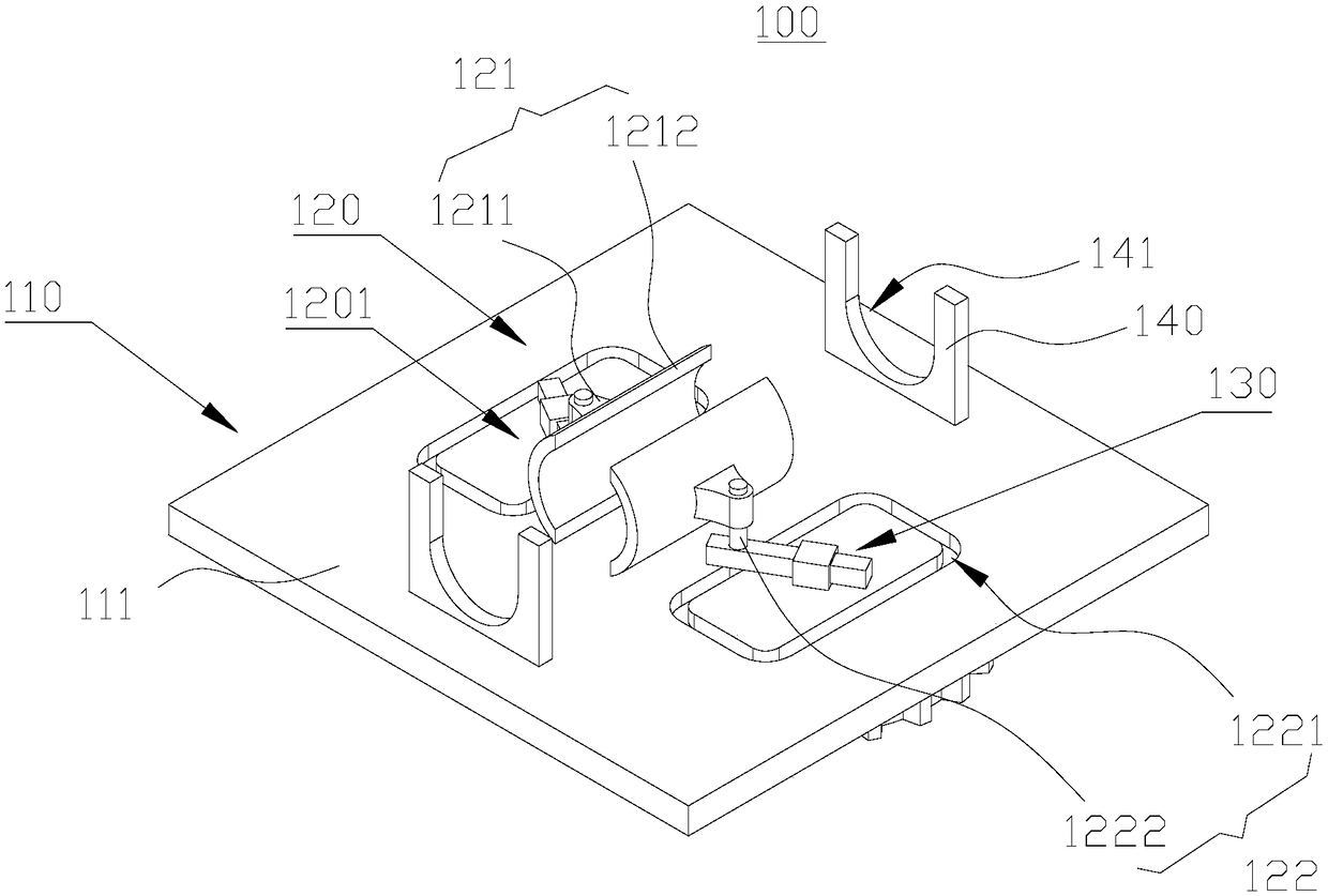
[0034] This embodiment provides an intermittent clamping and feeding device 100, refer to figure 1 As shown, a mounting table 110 and a clamping device 120 disposed on the mounting table 110 are included.

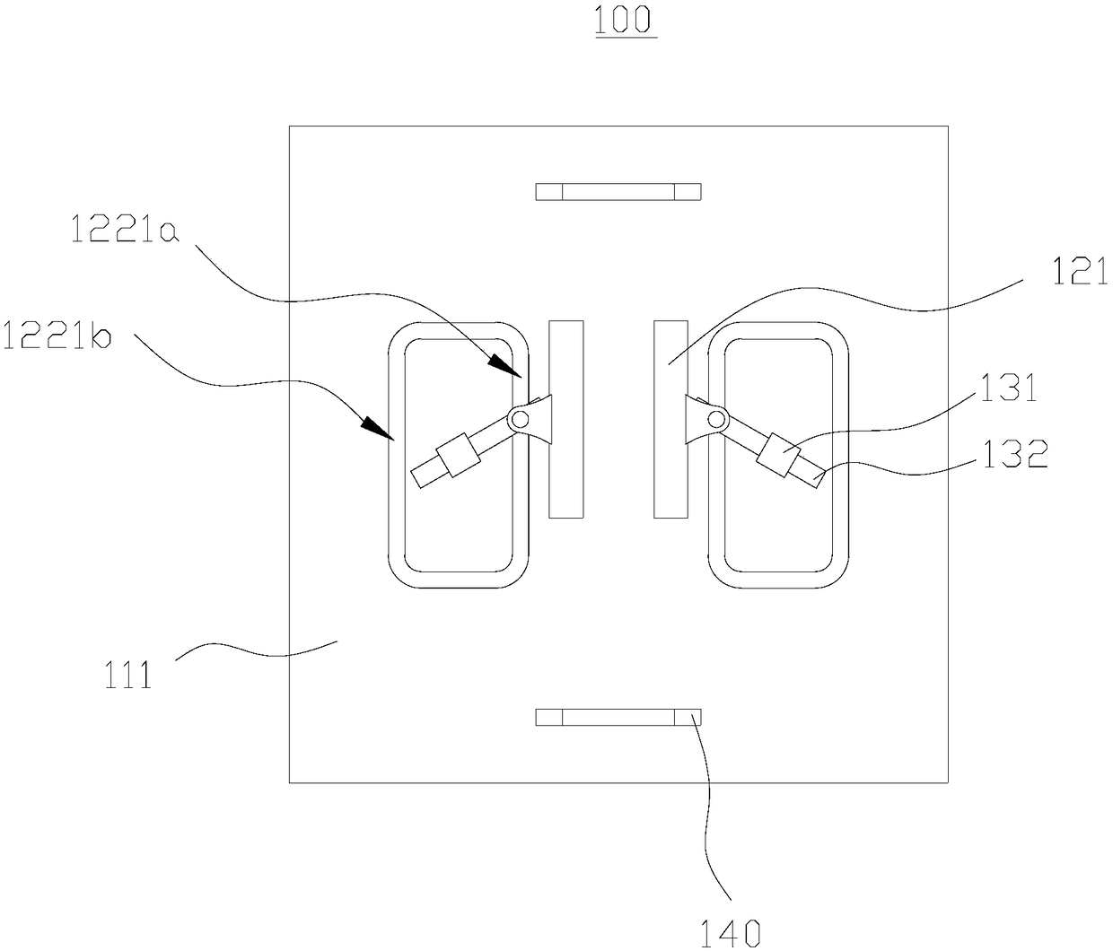
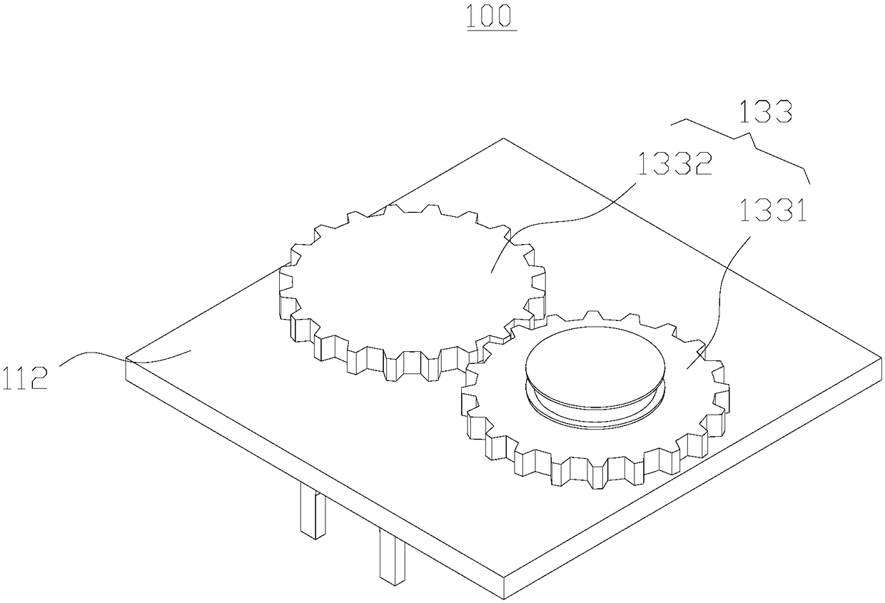
[0035] Such as figure 1 and figure 2As shown, the clamping device 120 includes a pair of clamping pieces 1201 that can approach or move away from each other, wherein each clamping piece 1201 includes a clamping arm 121 and a limiting mechanism 122 for limiting the movement of the clamping arm 121 . Each limiting mechanism 122 includes a limiting slot 1221 on the installation platform 110 and a connecting piece 1222 slidingly matched with the limiting slot 1221 . The limiting groove 1221 is annular, and one end of the connecting member 1222 is slidably embedded in the limiting groove 1221 , and the other end is connected to the clamping arm 121 . At the same time, each clamping part 1201 includes a driving device 130 for driving the connecting part 1222 to move along the...

no. 2 example

[0042] This embodiment provides a pipe cutting device 10, referring to Figure 5 As shown, a cutting device 200 and an intermittent clamping and feeding device 100 are included.

[0043] Such as Figure 5 As shown, the cutting device 200 includes a cutting frame 210 , and a cutting knife 220 and an extruding block 230 mounted on the cutting frame 210 . A cutting chamber 223 for placing pipes is formed between the cutter 220 and the extruding block 230 . The cutting is completed by intermittently clamping and feeding the tubular material into the cutting cavity 223 between the feeding device 100 .

[0044] In this embodiment, the tubular material is cut off by shearing between the cutter 220 and the extruding block 230 . Further, the side of the cutting knife 220 facing the extruding block 230 is bent into a "V" shape in a direction away from the extruding block 230 , forming a first cutting knife 221 and a second cutting knife 222 at a certain angle. During actual shearing...


PUM


Abstract

The invention discloses an intermittent clamping feeding device and tube cutting equipment, and belongs to the field of design cutting equipment. According to the intermittent clamping feeding device, movement tracks of two clamping arms are limited through two annular limiting grooves in parallel; a material is periodically clamped by the two clamping arms, and is pushed forwards, and thus the purpose of intermittent conveying can be achieved. The intermittent clamping feeding device is simple in structure, smart in design and very convenient to both use and maintain. The tube cutting equipment comprises a cutting device and the intermittent clamping feeding device, wherein the cutting device comprises a cutter, an extrusion block and a power device for driving the extrusion block to be close to or far away from the cutter; a cutting cavity for holding a tube is formed between the cutter and the extrusion block. The tube is intermittently pushed to the cutting cavity by using the intermittent clamping feeding device to complete cutting, tubes of uniform length sizes can be cut, the labor cost of manual material feeding is reduced, and the tube cutting equipment is relatively high in working efficiency, relatively high in size precision and simple and convenient to use.

Description

technical field [0001] The invention relates to the field of cutting equipment, in particular to an intermittent clamping and feeding device and pipe cutting equipment. Background technique [0002] The pipe cutting machine is a commonly used cutting equipment in the process of steel pipe processing. During the working process, it needs to intermittently transport the tubular material to the cutting part, so as to cut the tubular material into pipe fittings with basically equal lengths. [0003] In the prior art, some small workshops usually use manual feeding to locate the length of pipe fittings by visual inspection or pre-made marks, which has low precision and is labor-intensive. However, the existing pipe cutting machine with automatic sample feeding function involves computer program control, and the equipment is expensive. Contents of the invention [0004] The object of the present invention is to provide an intermittent clamping and feeding device, which realizes...

Claims


Application Information

Patent Timeline
Patent Type & Authority Patents(China)
IPC IPC(8): B23D33/02B23D21/00
CPCB23D21/00B23D33/02
Inventor 李殿波
Owner 延边通达实业有限责任公司
Learn More