Direct current micro-network line impedance detecting method and device for sagging control

A technology of line impedance and DC micro-grid, which is applied in the direction of measuring devices, measuring resistance/reactance/impedance, measuring electrical variables, etc., can solve the problem that load distribution and voltage quality are greatly affected by line impedance, and the central controller has high requirements. Communication lines increase system cost and other issues, to achieve the effect of improving voltage quality, low cost, and improving system reliability

Active Publication Date: 2017-06-23
SHANGHAI ZHIDA TECHNOLOGY DEVELOPMENT CO LTD
View PDF5 Cites 16 Cited by
  • Summary
  • Abstract
  • Description
  • Claims
  • Application Information

AI Technical Summary

Problems solved by technology

[0004] However, in droop control, load distribution and voltage control are often not compatible, and most of the existing control methods ignore the influence of line impedance, but in actual systems, line impedance is not completely negligible. It will affect load distribution and the quality of bus voltage. Existing solutions mostly use low-speed communication lines or sparse communication lines to exchange information between units, thereby achieving accurate load distribution.
[0005] 1. In a DC microgrid, load distribution and voltage quality a...

Method used


Image

  • Direct current micro-network line impedance detecting method and device for sagging control
  • Direct current micro-network line impedance detecting method and device for sagging control
  • Direct current micro-network line impedance detecting method and device for sagging control

Examples


Embodiment Construction

[0059] The present invention will be described in detail below in conjunction with the accompanying drawings and specific embodiments. This embodiment is carried out on the premise of the technical solution of the present invention, and detailed implementation and specific operation process are given, but the protection scope of the present invention is not limited to the following embodiments.

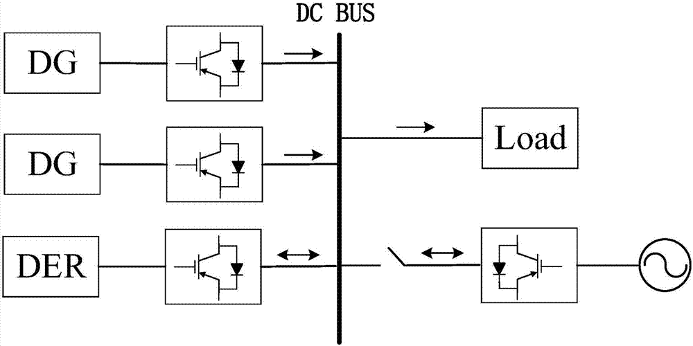
[0060] figure 1 Shown is a typical structure diagram of a DC microgrid. The DC bus (DC BUS) connects the grid, source, load, and storage together through lines. The grid, that is, the large power grid of the system, is connected to the microgrid through a bidirectional DC-AC converter and a circuit breaker. Whether the microgrid works on the grid or off-grid is related to this; Green energy sources such as photovoltaics and wind turbines are connected to the DC bus through a boost converter, and have two working modes: MPPT (Maximum Power Point Tracking) and constant voltage source; ...


PUM


Abstract

The invention relates to a direct current micro-network line impedance detecting method and device for sagging control. The method comprises the steps that S1 a plurality of groups of disturbance voltage signals are set and used as the reference voltage of a sagging controller; S2 output voltage and output current output by a DC-DC converter are measured; and S3 the line impedance between each distributed energy storage unit and a direct current bus is acquired according to a current-voltage relationship equation and multiple groups of output voltage and output current measured in the step S2; and the line impedance acquired in the step S3 is negatively compensated to the sagging resistor of the corresponding sagging controller. Compared with the prior art, the method and device have the advantages that the accurate measurement of the line impedance is realized without adding any additional measuring device on the basis of traditional sagging control; sagging coefficients are corrected to reduce the influence of the line impedance on sagging control; the load distribution rationality is ensured; the bus voltage quality is improved; and the system stability is improved.

Description

technical field [0001] The invention relates to the technical field of distributed power generation, in particular to a method and device for detecting the impedance of a DC micro-grid line for droop control. Background technique [0002] With the development of new energy, it has become an inevitable trend for large-scale photovoltaic wind turbines to be connected to the power grid, but the impact on the traditional power system cannot be ignored. As a form of efficient coordinated control of distributed power sources, microgrid can effectively reduce the distribution The impact of power sources on power systems. Microgrids can be divided into AC microgrids and DC microgrids according to different bus voltages. Compared with AC microgrid, DC microgrid has the characteristics of high efficiency, economy and simplicity, so it has received extensive attention. [0003] The microgrid consists of four parts: network, source, load, and storage. The main control goal is to coord...

Claims


Application Information

Patent Timeline
IPC IPC(8): G01R27/02
CPCG01R27/02
Inventor 赵晋斌刘琛张苏捷李吉祥李芬王闪闪
Owner SHANGHAI ZHIDA TECHNOLOGY DEVELOPMENT CO LTD
Why Eureka
Try Eureka