Reactive power voltage analysis method and system

A voltage analysis and voltage technology, applied in reactive power compensation, AC network voltage adjustment, reactive power adjustment/elimination/compensation, etc., can solve problems such as loss of low-voltage reactors, rise in substation bus voltage, loss of high-resistance, etc. Achieve the effect of reducing risk, ensuring availability, and strengthening maintenance work

Inactive Publication Date: 2017-06-23
SHANGHAI MUNICIPAL ELECTRIC POWER CO +1
View PDF0 Cites 0 Cited by
  • Summary
  • Abstract
  • Description
  • Claims
  • Application Information

AI Technical Summary

Problems solved by technology

When the UHV system is running, the voltage of the busbar in the substation may increase due to the loss of the low-voltage reactor after the main transformer is cut off or the high reactance is lost due to the cut-off of the line.
With the intensive feed-in of high-power DC in the 500kV power grid, during low-peak periods, especially during holidays, a large number of units need to be mediated in order to cope with peak regulation, which weakens the reactive power adjustment capability of the system and may cause the bus voltage to rise beyond the allowable value after the accident. Therefore, it is necessary to control the bus voltage

Method used


Image

  • Reactive power voltage analysis method and system
  • Reactive power voltage analysis method and system

Examples


Embodiment Construction

[0028] The present invention will be further elaborated below by describing a preferred specific embodiment in detail in conjunction with the accompanying drawings.

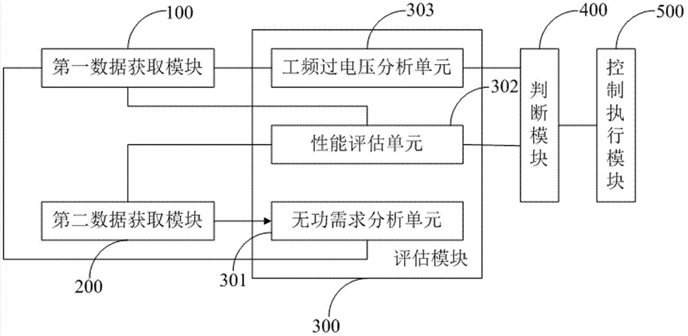
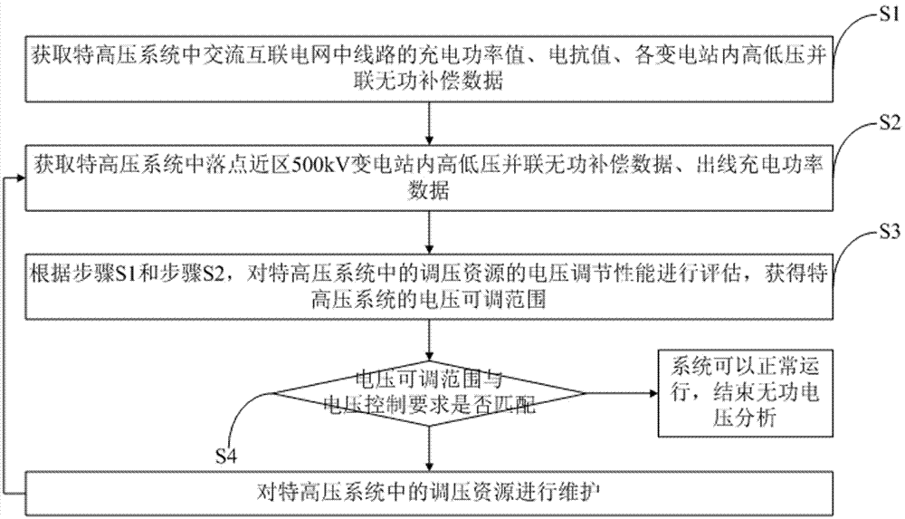
[0029] A reactive voltage analysis system used in UHV 1000 / 500kV systems, such as figure 1 As shown, the reactive power and voltage analysis system includes: a first data acquisition module 100, which is used to acquire the charging power value and reactance value of the lines in the AC interconnection grid in the UHV 1000 / 500kV system, and the high and low voltage parallel reactive power compensation in each substation. Data; the second data acquisition module 200 is used to obtain high and low voltage parallel reactive power compensation data and outgoing charging power data in the 500kV substation near the landing point in the UHV 1000 / 500kV system; the evaluation module 300 is respectively connected with the first The data acquisition module is connected with the second data acquisition module, and is used to...


PUM


Abstract

The invention discloses a reactive power voltage analysis method. The method comprises the following steps that: step S1, the charging power value and reactance value of a line in an alternating-current interconnected power grid in an ultra-high voltage 1000 / 500 kV system, as well as high-and low-voltage parallel reactive power compensation data of transformer substations are obtained; step S2, the high-and low-voltage parallel reactive power compensation data and outgoing charging power data of a location area 500 kV transformer substation in the ultra-high voltage 1000 / 500 kV system are obtained; step 3, the voltage adjustment performance of voltage adjustment resources in the system is evaluated, so that a voltage adjustable range can be obtained; and step 4, whether the voltage adjustable range can be matched with voltage control is judged, if the voltage adjustable range can be matched with the voltage control, the system can operate normally, reactive power voltage analysis is terminated, if the voltage adjustable range is not matched with the voltage control, the voltage adjustment resources in the system are maintained, the method returns to the step 3, and the sequence of the step 1 and step 2 can be reversed. The invention also provides a reactive power voltage analysis system. With the reactive power voltage analysis method and system of the invention adopted, reactive power voltage problems can be detected quickly and accurately, and the operational risks of the ultra-high voltage 1000 / 500 kV system can be effectively reduced.

Description

technical field [0001] The invention relates to the technical field of electric power system voltage automatic control, in particular to a reactive voltage analysis method and system. Background technique [0002] The power frequency overvoltage withstand capacity of 1000kV AC busbar is 1130kV, and the duration is 30 minutes. When the UHV system is running, the voltage of the substation bus may increase due to the loss of the low-voltage reactor after the main transformer is cut off or the high reactance is lost after the line is cut off. With the intensive feed-in of high-power DC in the 500kV power grid, during low-peak periods, especially during holidays, a large number of units need to be mediated in order to cope with peak regulation, which weakens the reactive power adjustment capability of the system and may cause the bus voltage to rise beyond the allowable value after the accident. Therefore, it is necessary to control the bus voltage. Contents of the invention ...

Claims


Application Information

Patent Timeline
Patent Type & Authority Applications(China)
IPC IPC(8): H02J3/16H02J3/18
CPCH02J3/16H02J3/1821Y02E40/30
Inventor 张开宇崔勇郭强冯煜尧张琪祁冯楠余颖辉苏运
Owner SHANGHAI MUNICIPAL ELECTRIC POWER CO
Why Eureka
Try Eureka