
Guiding type embedded drill bushing

An embedded and drill sleeve technology, applied in the field of machinery, can solve problems such as inability to assemble parts, difficult positioning, and deviation of drilling direction, and achieve the effects of improving assembly accuracy, simple structure, and accurate positioning

Inactive Publication Date: 2017-06-27
SHENYANG AIRCRAFT CORP
View PDF8 Cites 1 Cited by
  • Summary
  • Abstract
  • Description
  • Claims
  • Application Information

AI Technical Summary

Problems solved by technology

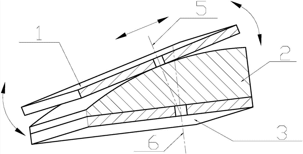
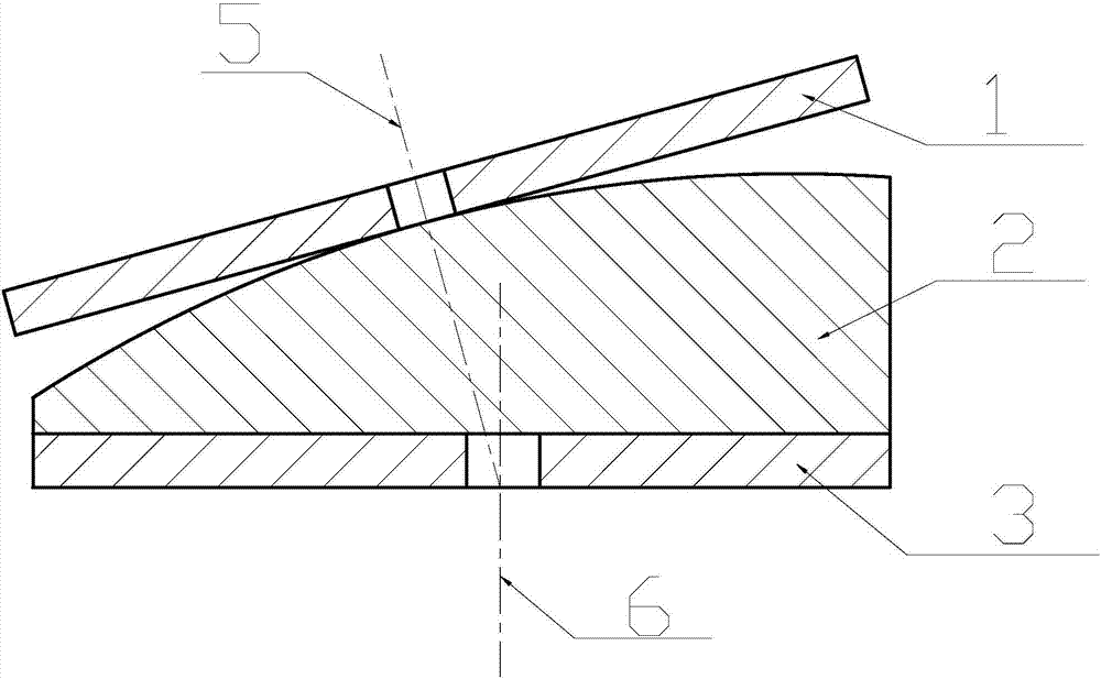
[0003] However, there are many curved surface parts in the aircraft manufacturing process (as shown in Figure 1(a), Figure 1(b)), and the hole positions are vector lines given according to the vector direction of the curved surface. Due to the certain rigidity of the template, such as Given a sample on the curved surface, the sample will slide or roll along the direction of the curved surface, making positioning difficult, so the hole position can only be given on the plane corresponding to the curved surface
But the vector line is not perpendicular to the taken plane, because the direction of the traditional drill casing hole is perpendicular to the sample plane, it will cause the deviation of the drilling direction
Once such templates are used to drill holes, parts cannot be assembled or assembly errors will be caused, which will affect product quality and reduce aircraft production efficiency

Method used


Image

  • Guiding type embedded drill bushing
  • Guiding type embedded drill bushing
  • Guiding type embedded drill bushing

Examples


Embodiment Construction

[0017] The present invention will be further described below in combination with specific embodiments.

[0018] Fig. 1(a) and Fig. 1(b) are the front view and front view of the traditional model drill bushing. In the figure 1 is the traditional model made on the curved surface, 2 is the part with one side of the curved surface, and 3 is the traditional no-angle Drill sleeve, 5 is the theoretical vector line of the part drilling, 6 is the vector line of the actual process hole.

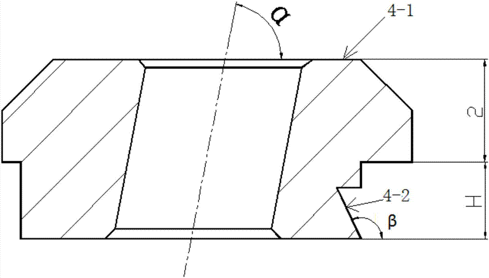
[0019] A guide type embedded drill sleeve, the main body of the drill sleeve is cylindrical, with a sleeve cap 4-1 with a thickness of 2mm, and a groove on the cylindrical surface that is in contact with the traditional sample plate 1 made on the curved surface 4-2, the cross section of the groove 4-2 is triangular, the wedge angle formed by the outer surface of the groove 4-2 and the vertical surface is 75°, and the drill sleeve and the template 2 are interference fit.

[0020] Under MBD technical co...


PUM


Abstract

The invention belongs to the technical field of machinery and provides a guide type embedded drill sleeve, which includes a cylindrical main body, a sleeve riser, a groove, and a drill sleeve boss. There is a groove with a triangular cross-section on the cylindrical surface where the guide type embedded drill sleeve contacts the template. The wedge angle formed by the outer surface of the groove and the vertical surface is 75°. There is interference between the guide type embedded drill sleeve and the template. Cooperate. There is a through hole in the center of the guided embedded drill sleeve, the angle α between the through hole and the vertical plane is 0°~75°, and there are 03.X.03 chamfers on both sides of the through hole. On the contact surface between the guide type embedded drill sleeve and the template, there is a drill sleeve boss which is symmetrical to the plane where the centerline of the through hole is located, to control the direction of drilling. The invention has a simple structure, adopts an asymmetric structure, and guides the drill bit to drill holes in the direction of the through hole, so that the drill bit can drill the process hole of the part according to the predetermined direction; the positioning is accurate, and the assembly precision is improved.

Description

technical field [0001] The invention belongs to the technical field of machinery and relates to a drill sleeve, in particular to an improvement of a drill sleeve for a model. Background technique [0002] With the development of digital production technology, the role of templates in the aircraft manufacturing process is becoming weaker and weaker. At this stage, it is mainly used for drilling assembly holes used for assembly and the guide hole or center hole of the part itself. When drilling the above-mentioned holes, first match the template with the parts, and then drill holes according to the hole positions on the drill sleeve of the template. [0003] However, there are many curved surface parts in the aircraft manufacturing process (as shown in Figure 1(a), Figure 1(b)), and the hole positions are vector lines given according to the vector direction of the curved surface. Due to the certain rigidity of the template, such as If the curved surface gives a template, the ...

Claims


Application Information

Patent Timeline
Patent Type & Authority Applications(China)
IPC IPC(8): B23B49/02
CPCB23B49/02
Inventor 宁俊义王志宏
Owner SHENYANG AIRCRAFT CORP
Learn More