Three-degree-of-freedom water cooling workbench for TIG automatic surfacing
A technology of automatic surfacing and degree of freedom, applied in the direction of manufacturing tools, welding equipment, welding accessories, etc., can solve the problem of lack of inability and other problems, and achieve the effect of high forming accuracy, precise control of speed and position, and high motion accuracy.
- Summary
- Abstract
- Description
- Claims
- Application Information
AI Technical Summary
Problems solved by technology
Method used
Image
Examples
Embodiment 1
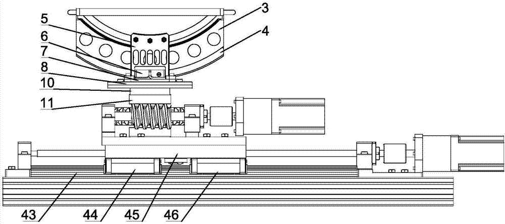
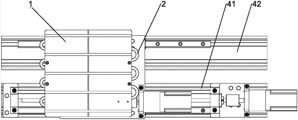
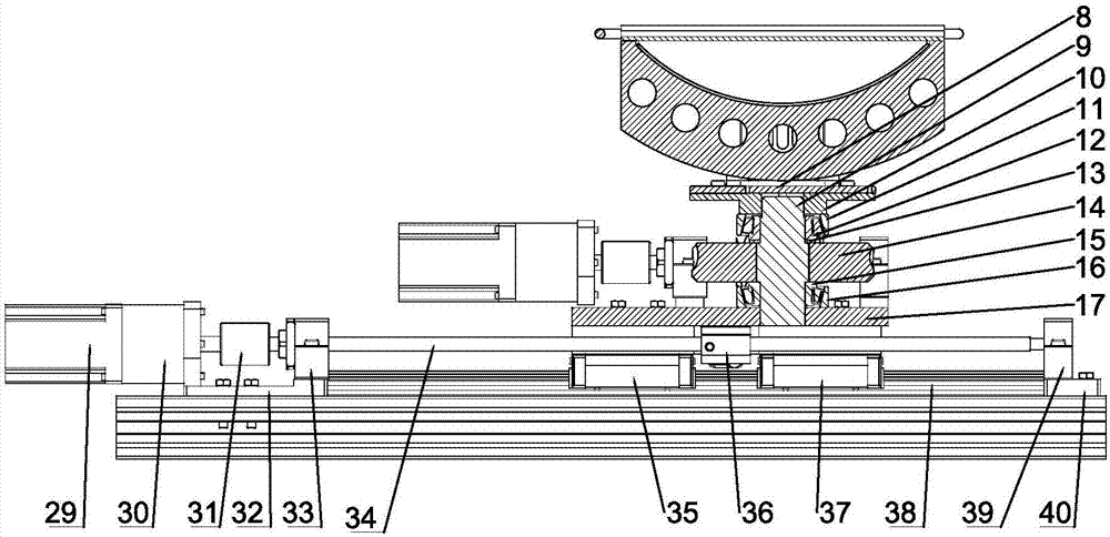
[0031] refer to Figure 1 to Figure 4 , a three-degree-of-freedom water-cooled workbench for TIG automatic surfacing welding of the present invention includes: an upper swing mechanism, a middle slewing mechanism, a lower linear feed mechanism, and a base, and the lower linear feed mechanism is installed through slide rails On the base, the upper swing mechanism and the middle swing mechanism are superimposed on the lower linear feed mechanism from top to bottom, and the lower linear feed mechanism drives the middle swing mechanism and the upper swing mechanism to perform linear motion, and the middle swing mechanism The upper swing mechanism is driven to perform a rotary motion, and the upper swing mechanism performs a left and right swing motion.
[0032] The upper swing mechanism includes: workbench body 1, fan-shaped swing piece 3, and swing drive system. There are a number of parallel round holes inside the workbench body 1 for installing the cooling waterway 2. The cooli...
Embodiment 2
[0034] The difference between embodiment 2 and embodiment 1 is that the middle rotary mechanism adopted in embodiment 2 mainly adopts a worm gear mechanism.
[0035]The central slewing mechanism includes: a worm gear mechanism, a turntable base 17 and a worm drive system, and the worm drive system includes: a worm servo motor 28, a worm coupling 24 and a worm reducer 26, and the worm servo motor 28 is connected to the worm reducer 26 through screws , the output shaft of the worm reducer 26 is connected with the worm 21 through the worm coupling 24, at the same time, the worm 21 is fixed on the turntable base 17 through the worm bk seat 18 and the worm bf seat 22, and the worm reducer 26 is fixed on the worm reducer seat 25 On the turntable base 17, the function of the worm bk seat block 20 and the worm bf seat block 23 is to raise the worm 21 to ensure that the output shaft of the worm 21 and the worm reducer 26 are coaxial, thereby ensuring that the worm servo motor 28 can dri...
Embodiment 3
[0037] The difference between embodiment 3 and embodiment 1 is that the lower linear feed mechanism adopted in embodiment 3 mainly adopts a screw nut mechanism.
[0038] The lower linear feed mechanism includes: a lead screw nut mechanism and a lead screw drive system, the lead screw drive system includes: a lead screw servo motor 29, a lead screw coupling 31 and a lead screw reducer 30,
[0039] The lead screw 34 is installed above the slide rail, and the lead screw servo motor 29 installed on the lower side of the turntable base 17 is fixed on the lead screw reducer 30 by screws, and one side of the lead screw coupling 31 is connected to the output of the lead screw reducer 30 shaft, the other side is connected on the leading screw 34. Leading screw 34 is matched with leading screw nut 36, and leading screw nut 36 is fixed on the turntable base 17 by screw. The leading screw 34 is fixed on the aluminum profile base 1 41 through the leading screw bf seat 33 and the leading s...
PUM
 Abstract
Description
Claims
Application Information
 - R&D
- Intellectual Property
- Life Sciences
- Materials
- Tech Scout
- Unparalleled Data Quality
- Higher Quality Content
- 60% Fewer Hallucinations
Browse by: Latest US Patents, China's latest patents, Technical Efficacy Thesaurus, Application Domain, Technology Topic, Popular Technical Reports.
© 2025 PatSnap. All rights reserved.Legal|Privacy policy|Modern Slavery Act Transparency Statement|Sitemap|About US| Contact US: help@patsnap.com


