Treatment method for shear lag of inverted U-shaped composite beam

A processing method combined with beam technology, applied in electrical digital data processing, special data processing applications, bridges, etc., can solve problems such as sudden changes in boundary conditions, inability to completely solve, constant changes in load and shear lag displacement boundary conditions, etc., to achieve The effect of improving accuracy, reducing the amount of calculation, and facilitating operation and programming

Inactive Publication Date: 2017-06-27
CHONGQING UNIV
View PDF8 Cites 13 Cited by
  • Summary
  • Abstract
  • Description
  • Claims
  • Application Information

AI Technical Summary

Problems solved by technology

But the disadvantage of these two patents is that they are limited to the structural differential equations and boundary conditions derived from the energy method, and still cannot be applied to the shear lag analysis of the complex cable-stayed bridge construction process
[0007] For П-shaped composite girder cable-stayed bridges, the sudden change of the shear lag displacement boundary conditions caused by the concentrated bending moment of the main girder (cable anchor point eccentricity and prestressed anchorage eccentricity), the load and displacement during the dynamic construction process The problem of changing shear lag displacement boundary conditions cannot be completely solved by the above methods
Since the existing technology is limited to simple structural analysis under a single working condition, it cannot solve the construction error problem caused by the shear lag effect in the dynamic process of cable-stayed bridge construction

Method used

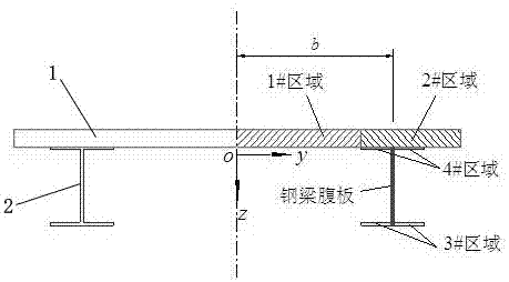
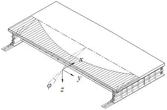
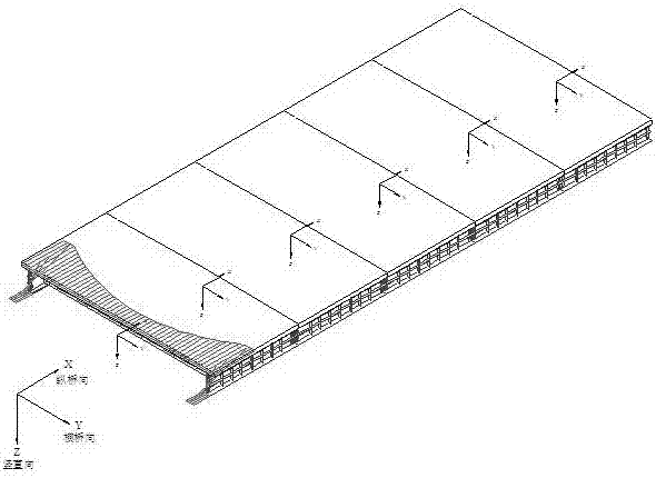

Image

  • Treatment method for shear lag of inverted U-shaped composite beam
  • Treatment method for shear lag of inverted U-shaped composite beam
  • Treatment method for shear lag of inverted U-shaped composite beam

Examples


Embodiment

[0171] Figure 5 is a span layout of a cable-stayed bridge, Image 6 Dimension drawing for the cross-section of the cable-stayed bridge. Depend on Figure 5 and Image 6 The span layout of the cable-stayed bridge and the section size of the main girder are shown in Table 1, and the size specifications of the steel plate parts of each beam section are shown in Table 2.

[0172] Table 1 Span dimensions and main girder section dimensions of cable-stayed bridges

[0173]

[0174] Table 2 Dimensions of steel plates for each beam section (mm)

[0175]

[0176] Note: The beam segment type numbers in Table 2 are used to identify different types of segments. A segment formed in the construction cycle of a cable-stayed bridge, and the size of each component of each segment will change according to the requirements. In order to identify each type of segment, the beam segment type number is introduced to pair beams with the same size Sections are numbered.

[0177] Calculate ...


PUM


Abstract

The invention discloses a treatment method for shear lag of an inverted U-shaped composite beam. According to the treatment method for the shear lag of the inverted U-shaped composite beam, a shear lag warping displacement mode is reasonably supposed for section structure characteristics of the inverted U-shaped composite beam; on the basis of the minimum potential energy principle, an equilibrium equation in the variational form is established; and the continuous variational equilibrium equation is converted into a discrete finite beam segment method through introducing displacement interpolation functions of two shear lag freedom degrees of each node so as to obtain an element stiffness matrix which considers the shear lag effect. A related application program is written to carry out fine analysis on the construction process of an inverted U-shaped composite beam cable-stayed bridge. The treatment method for the shear lag of the inverted U-shaped composite beam has the advantages that shear lag displacement boundary condition mutation caused by concentrated bending moment in the cable-stayed bridge can be treated, the stress state of girder section in the construction process can be really reflected and the accuracy of the construction process of the inverted U-shaped composite beam cable-stayed bridge can be improved. The treatment method for the shear lag of the inverted U-shaped composite beam has the advantages of clear mechanical conception, simple calculation and broad application prospect and is a useful addition to the shear lag treatment method in the current specifications.

Description

technical field [0001] The invention belongs to the technical field of bridge construction control, and in particular relates to a processing method for the shear hysteresis effect of a Π-shaped combined beam in the construction control process of a cable-stayed bridge. Background technique [0002] With the rapid development of the national economy, the requirements for the spanning capacity of cable-stayed bridges are getting higher and higher. Therefore, steel truss girders, prestressed concrete П-shaped beams or "double I-beam + concrete slabs" are more used in the design. Π-shaped combined beam. The Π-shaped combined beam can give full play to the respective advantages of steel and concrete and is convenient for construction, so it has broad development prospects. However, the “width-to-height ratio” of Π-shaped combined beams is relatively large, especially the width of the roof between the two webs is much larger than that of the roof between the webs of the box gird...

Claims


Application Information

Patent Timeline
Patent Type & Authority Applications(China)
IPC IPC(8): E01D11/04E01D19/12G06F17/50E01D101/30E01D101/24
CPCE01D11/04E01D19/12E01D2101/24E01D2101/30G06F30/13G06F2119/06
Inventor 周世军宋刚
Owner CHONGQING UNIV
Why Eureka
Try Eureka