
Single-side rotational flow speed-increasing tool for drilling fluid of deep well drilling bottom

A drilling fluid and drilling technology, applied in wellbore/well components, earth-moving drilling, flushing wellbore, etc., can solve the problems of decreased ROP, obstructing the timely removal of bottom-hole cuttings, and increased drill bit wear, etc. ROP, shortening the drilling time of a single well, and reducing the effect of drilling costs

Inactive Publication Date: 2017-06-27
CNPC DRILLING RES INST +1
View PDF13 Cites 2 Cited by
  • Summary
  • Abstract
  • Description
  • Claims
  • Application Information

AI Technical Summary

Problems solved by technology

The main reason is that the bottom hole pressure difference has a holding effect on the newly broken cuttings, which hinders the timely removal of bottom hole cuttings, affects the rock breaking efficiency of the drill bit, reduces the ROP, and intensifies the wear of the drill bit

Method used


Image

  • Single-side rotational flow speed-increasing tool for drilling fluid of deep well drilling bottom
  • Single-side rotational flow speed-increasing tool for drilling fluid of deep well drilling bottom

Examples


Embodiment Construction

[0015] The following is attached figure 1 , describe the present invention in detail, as follows:

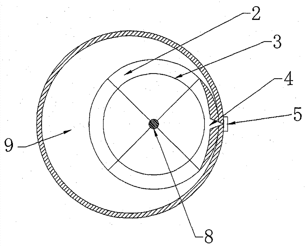
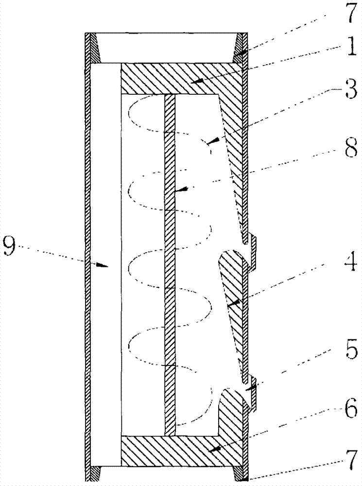
[0016] The deep well drilling bottomhole drilling fluid unilateral swirl speed-up tool consists of a liquid inlet 1, a support rod 2, a helical impeller 3, a V-shaped groove 4, a solid discharge injection port 5, a liquid outlet 6 and a screw thread 7.

[0017] Drilling fluid is pressurized and pumped from the ground into the ground, and is divided into two parts when it flows from the upper drill pipe through the deep well drilling bottom hole drilling fluid single side swirl speed increasing tool: one part passes through the bottom hole drilling fluid single side swirl speed increasing tool of deep well drilling The space 9 flows out directly; the other part flows from the liquid inlet 1 into the deep well drilling bottom hole drilling fluid unilateral swirling speed-up tool.

[0018] The drilling fluid that flows into the deep well drilling bottom hole drilling fluid through...


PUM


Abstract

The invention relates to a single-side rotational flow speed-increasing tool for drilling fluid of the deep well drilling bottom. The single-side rotational flow speed-increasing tool is mainly composed of a liquid inlet, supporting rods, a helical impeller, V-shaped grooves, solid discharging injection ports and a liquid outlet. According to the tool, the problems of high density of the drilling fluid of the deep well drilling bottom, the serious pressure holding effect and the low mechanical drilling speed are solved. The concrete implementation process of the single-side rotational flow speed-increasing tool for the drilling fluid of the deep well drilling bottom comprises the following steps that when the drilling fluid flowing from top to bottom flows through the single-side rotational flow speed-increasing tool for the drilling fluid of the deep well drilling bottom, part of the drilling fluid directly flows out from the space out of the single-side rotational flow speed-increasing tool for the drilling fluid of the deep well drilling bottom, and the other part of the drilling fluid flows into the single-side rotational flow speed-increasing tool for the drilling fluid of the deep well drilling bottom from the liquid inlet. The high-pressure and high-speed drilling fluid impacts the helical impeller of the single-side rotational flow speed-increasing tool for the drilling fluid of the deep well drilling bottom to rotate in high speed, the helical impeller rotatably transports solid particles in the drilling fluid into the V-shaped grooves, and after collected the by the V-shaped grooves, the separated solid particles are injected out of drilling rods from the two upper and lower solid discharging injection ports. The tool can effectively reduce the pressure holding effect in the deep well bottom, the mechanical drilling speed is improved, and the cost is reduced.

Description

technical field [0001] The invention relates to a single-side swirling speed-increasing tool for drilling fluid at the bottom of deep well drilling, which belongs to a supporting device for oil and natural gas drilling, and in particular can reduce the density of drilling fluid at the bottom of deep well drilling, reduce drill bit wear, increase drilling speed, and prolong the life of the drill bit. Background technique [0002] With the reduction of shallow oil and gas resources in the world, oil and gas exploration and development are gradually shifting to deep wells. The speed of drilling in deep formations directly affects the economic benefits of oil and gas exploration and development. However, deep drilling is subject to high formation pressure and requires a high density of drilling fluid. High-density drilling fluid greatly affects the speed of penetration. Urgent problems. [0003] As the drilling process continues and the drilling depth continues to increase, it ...

Claims


Application Information

Patent Timeline
Patent Type & Authority Applications(China)
IPC IPC(8): E21B21/06
CPCE21B21/065
Inventor 刘明鑫任威严查永进葛云华王灵碧张建忠邱心明韩树
Owner CNPC DRILLING RES INST
Learn More