
A progressive shield type gas pressure relief and extraction method

A gas and drainage technology, applied in the field of progressive shielding gas pressure relief and drainage, can solve the problems of increasing the influence range and pressure relief effect of through-layer drilling, poor applicability of drilling pressure relief and permeability enhancement technology, etc. The effect of decompression and anti-reflection, avoiding the elimination of blank strips, and improving the driving speed

Active Publication Date: 2018-09-25
CHINA UNIV OF MINING & TECH
View PDF6 Cites 0 Cited by
  • Summary
  • Abstract
  • Description
  • Claims
  • Application Information

AI Technical Summary

Problems solved by technology

[0003] Technical problem: The purpose of the present invention is to overcome the deficiencies in the prior art and provide a safe, efficient and economical solution that can effectively solve the problem of poor applicability of the existing drilling pressure relief and anti-reflection technology, combined with hydraulic punching With the technical advantages of hydraulic slotting, the coupling mode of ordinary drilling and "drilling-punching-cutting" drilling under the condition of floor penetration is established, and the drilling is divided into partition holes, cover holes and pressure relief holes. The sequence of hole construction and its spatial location increase the impact range and pressure relief effect of drilling through layers, thereby realizing efficient regional gas drainage

Method used


Image

  • A progressive shield type gas pressure relief and extraction method
  • A progressive shield type gas pressure relief and extraction method

Examples


Embodiment Construction

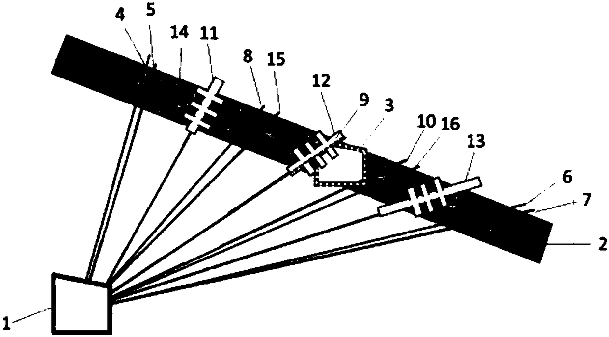
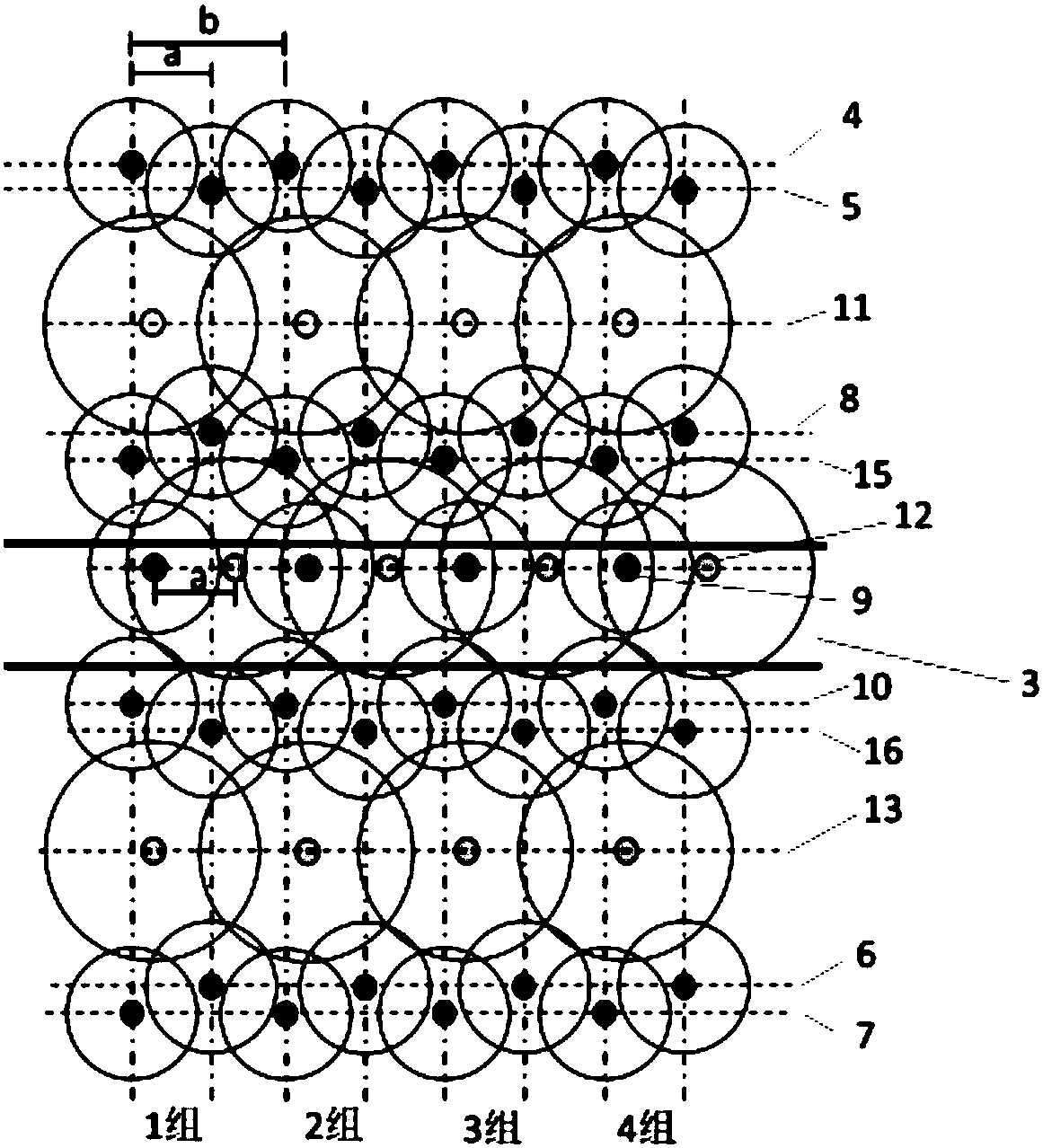
[0020] The progressive shielding gas pressure relief and drainage method of the present invention includes the following steps:

[0021] a. From the floor roadway 1 to the coal seam 2 on both sides of the upper coal roadway 3, the upper and lower partition holes shall be constructed through the layer; the upper and lower partition holes shall each be at least two, and the holes between the upper partition holes The gap and the hole spacing a between the upper partition holes are 2.5-3.5m respectively.

[0022] b. Pre-drain the gas from the upper partition hole and the lower partition hole. The upper partition hole separates the gas from the coal roadway and the upper side gas moves to the coal road 3, and the lower partition hole separates the gas from the coal roadway and lowers the gas to the coal roadway. 3 transport;

[0023] c. Between the upper partition hole and the lower partition hole, a plurality of through-layer shield holes are constructed at intervals from the floor roa...


PUM


Abstract

The invention provides a progressive shielding type gas depressurizing extraction method which is particularly suitable for depressurizing outburst elimination extraction of coal roadway strip gas in a soft high-outburst coal seam through seam-penetration drilling holes. The seam-penetration drilling holes are constructed in the portions, on the two sides of an upper coal roadway, of the coal seam from a base plate roadway. Since the high-gas-outburst coal seam has high outburst tendency, the depressurizing permeation increasing measure of direct drilling hole construction can cause severe disturbance to an original coal body to induce a hole jetting phenomenon, the coupling mode of common drilling holes and punching and cutting drilling holes under the condition of base plate seam penetration is built, and the drilling holes are divided into the partition holes, the shielding holes and the depressurizing holes. Through reasonable arrangement of the common seam-penetration drilling holes and the drilling, punching and cutting drilling coupled depressurizing drilling holes, the gas extraction effect of the area coal body is improved, the phenomena of an outburst elimination blanking zone and hole jetting are voided, the drilling construction speed in remarkably increased, and the gas extraction effect is remarkably improved, and the technology has good adaptability to all coal seams of different occurrence states.

Description

Technical field [0001] The invention relates to a progressive shield type gas pressure relief extraction method, which is especially suitable for coal seam areas where gas pressure reaches 2.0 MPa or dynamic phenomena occur during drilling, and belongs to the technical field of coal seam mining with high gas outburst. Background technique [0002] The coal seams with high gas outburst in my country have the characteristics of microporosity, low permeability, and high adsorption, which make pre-mining gas pre-drainage difficult and poor gas pre-drainage effect. Therefore, special measures must be taken to increase coal seam permeability and increase gas drainage rate. Hydraulic cutting, hydraulic punching and other hydraulic measures are currently the main pressure relief and permeability enhancement methods. By destroying the coal in the borehole, a pressure relief space is formed, which increases the permeability of the surrounding coal. However, due to the complex occurrence of...

Claims


Application Information

Patent Timeline
Patent Type & Authority Patents(China)
IPC IPC(8): E21F7/00E21B43/26
CPCE21B43/26E21F7/00
Inventor 林柏泉刘统王一涵李贺杨威刘厅高亚斌胡欣然
Owner CHINA UNIV OF MINING & TECH
Learn More