Diagnosis method for energy saving at cold end of condensing steam turbine

A technology of energy-saving diagnosis and steam turbine, which is applied in the direction of engine function, mechanical equipment, engine components, etc., and can solve problems such as not considering the cleanliness of the condenser, mutual interference, lack of cleanliness of the condenser in the power plant, etc.

Active Publication Date: 2018-05-01
STATE GRID CORP OF CHINA +2
View PDF2 Cites 0 Cited by
  • Summary
  • Abstract
  • Description
  • Claims
  • Application Information

AI Technical Summary

Problems solved by technology

For a running unit, except that the characteristics of the condenser remain unchanged, the other cold-end parameters are constantly changing with the operation adjustment, external environment and unit load; It may be beneficial to start the backup circulating pump when the condenser is clean, but it may be disadvantageous to start the backup circulating pump when the condenser is clean
These problems increase the difficulty of energy saving work at the cold end
[0003] The Beerman formula of the former Soviet Thermal Engineering Research Institute and the "Standards for SteamSurface Condensers" formulated by the American Society of Heat Transfer can calculate the influence of various cold-end factors on the back pressure, but these methods require all accurate cold-end parameters , and most power plants lack real-time parameters such as condenser cleanliness, making it difficult to quantify and calculate the economics of cold-end adjustment or transformation in real time
At present, the cold end optimization of thermal power plants mostly relies on the experience of operating personnel. Some power plants also conduct condenser performance tests without considering changes in condenser cleanliness. However, if this method takes a long time, the test results may be invalid.

Method used


Image

  • Diagnosis method for energy saving at cold end of condensing steam turbine
  • Diagnosis method for energy saving at cold end of condensing steam turbine
  • Diagnosis method for energy saving at cold end of condensing steam turbine

Examples


Embodiment 1

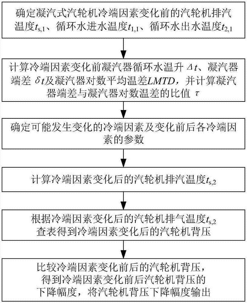
[0048] Such as figure 1 As shown, the implementation steps of the method for diagnosing energy saving at the cold end of a condensing steam turbine in this embodiment include:

[0049] 1) Determine the exhaust steam temperature t of the condensing steam turbine before the energy-saving related cold-end factors change s,1 , circulating water inlet temperature t 1,1 , Circulating water outlet temperature t 2,1 (where the steam turbine exhaust temperature t s,1 It can be measured directly under the condition of ensuring the measurement accuracy, or can be obtained by measuring the back pressure of the steam turbine based on the preset water and steam property table or enthalpy entropy diagram), and calculate the condenser before the cold end factor changes from the above data Circulating water temperature rise Δt, condenser end difference δt and condenser logarithmic mean temperature difference LMTD, and calculate the ratio of condenser end difference to condenser logarithmic ...

Embodiment 2

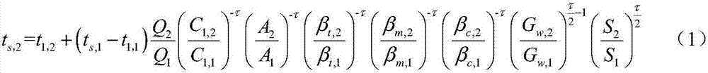
[0134] This embodiment is basically the same as Embodiment 1, the main difference is: calculate the exhaust steam temperature t of the steam turbine after the cold end factor changes s,2 The formulas are different. In this example, on the basis of formula (1), it is assumed that the characteristics of the condenser remain unchanged, and the cleanliness of the condenser remains unchanged in a short period of time. For example, it is assumed that the circulating water inlet temperature and the heat load of the condenser Also unchanged, formula (1) is simplified to get formula (5), and formula (5) is used to calculate the exhaust steam temperature t of the steam turbine after the cold end factor changes s,2 .

[0135]

[0136] In formula (5), t s,1 and t s,2 respectively represent the exhaust steam temperature of the steam turbine before and after the change of the cold end factor, t 1 Indicates the circulating water inlet temperature, G w,1 and G w,2 Respectively represe...

Embodiment 3

[0138] This embodiment is basically the same as Embodiment 1, the main difference is: this embodiment is for cooling tower transformation, and calculates the exhaust steam temperature t of the steam turbine after the cold end factor changes s,2 The formulas are different. In this embodiment, on the basis of formula (1), it is considered that the characteristics of the condenser remain unchanged, and the cleanliness of the condenser remains unchanged in a short period of time. For example, it is assumed that the circulating water flow rate and the heat load of the condenser , simplify the formula (1) to get the formula (6), and use the formula (6) to calculate the exhaust steam temperature t of the steam turbine after the cold end factor changes s,2 .

[0139]

[0140] In formula (6), t s,1 and t s,2 respectively represent the exhaust steam temperature of the steam turbine before and after the change of the cold end factor, t 1,1 and t 1,2 Respectively represent the circ...


PUM


Abstract

The invention discloses a cold end energy conservation diagnosis method for a condensing steam turbine. The cold end energy conservation diagnosis method for the condensing steam turbine comprises the following steps that the exhaust steam temperature (or the back pressure of the turbine), existing before cold end factors change, of the condensing steam turbine is measured; the circulating water inlet and outlet temperatures existing before the cold factors change are measured; the cold end factors which are possible to change are determined, and the parameters, existing before changing and after changing, of each cold end factor are determined; and the exhaust steam temperature existing after the cold end factors change, of the condensing steam turbine is calculated according to the parameters, and the decrease amplitude, generated after the cold factors change, of the back pressure of the condensing steam turbine is obtained. The cold end energy conservation diagnosis method for the condensing steam turbine has the advantages that calculation is easy, the number of needed parameters is small, the precision is high, and implementation is easy; and the defect that during existing cold end energy conservation diagnosis, all the cold end variables are needed is overcome, and real-time high-precision cold end energy conservation diagnosis is achieved.

Description

technical field [0001] The invention relates to the technical field of electric power engineering, in particular to an energy-saving diagnosis method for a cold end of a condensing steam turbine. Background technique [0002] In the thermodynamic cycle of a modern large-scale power station condensing steam turbine unit, the condenser is the core, the low-pressure cylinder of the steam turbine is connected internally, and the water supply system is externally connected to form the cold end system of the power plant. The condenser pressure (i.e. the back pressure of the steam turbine) has a great influence on the economics of the unit. How to reduce the back pressure of the unit as much as possible within the allowable range of the external environment is a crucial task for thermal power plants to save energy. The cold-end factors affecting back pressure mainly include circulating water inlet temperature, circulating water flow rate, condenser cleanliness, condenser thermal lo...

Claims


Application Information

Patent Timeline
Patent Type & Authority Patents(China)
IPC IPC(8): F01D21/00G06F17/50
CPCF01D21/00F01D21/003F05D2260/80G06F30/17
Inventor 徐曙蒋北华程贵兵李明焦庆丰
Owner STATE GRID CORP OF CHINA
Why Eureka
Try Eureka