
Fiber reinforced composite material high-pressure gas bottle with superconduction radiating device

A technology of high-pressure gas cylinder and heat-dissipating device, which is applied in the direction of equipment loaded into pressure vessel, installation device of vessel structure, pressure vessel, etc., can solve the problems of thermal conductivity limiting heat transfer efficiency, reducing heat transfer efficiency, heat loss, etc. Achieve the effect of high filling rate, wide adaptability and fast heat dissipation

Inactive Publication Date: 2017-06-27
ZHEJIANG UNIV
View PDF10 Cites 6 Cited by
  • Summary
  • Abstract
  • Description
  • Claims
  • Application Information

AI Technical Summary

Problems solved by technology

For example, EP1717511 uses strong heat-conducting materials such as copper or aluminum to export the heat generated in the container, but the thermal conductivity of the materials used limits the heat transfer efficiency; The transfer property achieves the purpose of transferring the heat generated inside the gas cylinder, but the heat pipe is convective in nature and has heat loss, thus reducing the heat transfer efficiency

Method used


Image

  • Fiber reinforced composite material high-pressure gas bottle with superconduction radiating device
  • Fiber reinforced composite material high-pressure gas bottle with superconduction radiating device
  • Fiber reinforced composite material high-pressure gas bottle with superconduction radiating device

Examples


Embodiment Construction

[0026] The present invention will be further described below in conjunction with the accompanying drawings and specific embodiments.

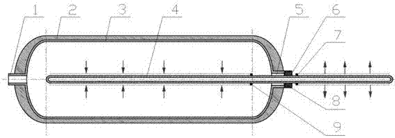
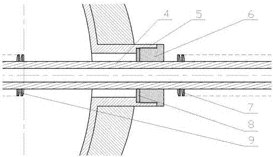
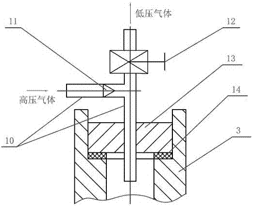
[0027] like figure 1 , figure 2 , image 3 As shown, the inner liner 3 of the high-pressure gas cylinder of the present invention is surrounded by a fiber winding layer 2, and one end of the high-pressure gas cylinder has an air inlet and outlet 1, and the other end of the high-pressure gas cylinder has an opening 5, which is exposed on the high-pressure gas cylinder. One end of the outer opening 5 is threadedly connected to the opening end cap 6, and an opening sealing gasket 8 is provided between the opening end cap 6 and the opening 5, and one end of the superconducting heat pipe 4 passes through the opening end cap 6 central hole through the opening sealing gasket 8 Insert into the high-pressure gas cylinder, the other end of the superconducting heat pipe 4 is located outside the high-pressure gas cylinder, the superconducting heat pipe ...


PUM


Abstract

The invention discloses a fiber reinforced composite material high-pressure gas bottle with a superconduction radiating device. One end of the high-pressure gas bottle is provided with a gas in-out opening, the other end of the high-pressure gas bottle is provided with an opening, one end of a superconduction heat pipe is inserted into the high-pressure gas bottle, the other end of the superconduction heat pipe is located outside the high-pressure gas bottle, fins are arranged outside the superconduction heat pipe, and an inorganic salt superconduction medium is inflated into the pipe; the first end of a three-way pipe penetrates a center hole of a gas in-out opening end cap to be inserted into the high-pressure gas bottle through a front sealing gasket, the second end of the three-way pipe is provided with a high-pressure gas inlet through a one-way valve, and the third end of the three-way pipe is provided with a low-pressure gas outlet through a reducing valve. Or only one end of the high-pressure gas bottle is provided with the gas in-out opening, and one end of the superconduction heat pipe penetrates the center hole of the gas in-out opening end cap to be inserted into the high-pressure gas bottle through the front sealing gasket. In the air inflation process of the fiber reinforced composite material high-pressure gas bottle, measures such as precooling are not needed, and energy consumption is reduced; under the same temperature limitation, the higher filling rate can be achieved; and compared with existing metal tube radiators and heat pipe radiators at home and abroad, the radiating speed is higher, and adaptability is wider.

Description

technical field [0001] The invention relates to a high-pressure gas cylinder, in particular to a fiber-reinforced composite material high-pressure gas cylinder with a superconducting cooling device. Background technique [0002] The rapid inflation and deflation technology is directly connected to the high-pressure gas cylinder by a large-volume high-pressure gas cylinder or a high-pressure pump, and the valve is opened for inflation. This method has a fast inflation speed, which can reach several kilograms per minute. However, the filling and discharging speed of high-pressure gas cylinders is not as fast as possible, which is mainly determined by the temperature effect when the gas is quickly charged and discharged. The faster the filling speed, the more obvious the temperature rise. The strength of the material matrix will have a greater impact, thereby affecting the strength of the composite gas cylinder, so it is necessary to control the temperature rise when the high-...

Claims


Application Information

Patent Timeline
Patent Type & Authority Applications(China)
IPC IPC(8): F17C1/06F17C5/06F17C13/00F17C13/06
CPCF17C1/06F17C5/06F17C13/002F17C13/06F17C2203/0604F17C2203/0609F17C2203/0619F17C2203/0643F17C2203/0646F17C2203/0648F17C2203/0663F17C2205/0311F17C2260/023
Inventor 郑传祥吴嘉懿陈学东范志超江勇连娇愿
Owner ZHEJIANG UNIV
Learn More