
A printed circuit board molten salt heat exchanger with double-layer plate arrangement

A technology of printed circuit boards and double-layer boards is applied in the field of heat exchange devices, which can solve the problems of shortening the service life of heat exchangers, large thermal expansion effect of heat exchanger flow channels, etc. The effect of improving and reducing pressure loss

Active Publication Date: 2020-02-07
SHANGHAI ADVANCED RES INST CHINESE ACADEMY OF SCI
View PDF8 Cites 0 Cited by
  • Summary
  • Abstract
  • Description
  • Claims
  • Application Information

AI Technical Summary

Problems solved by technology

Taking binary nitrate as an example, its melting point is 207°C, and its complete melting temperature is 238°C. When the molten salt is lower than 238°C, solid crystals will appear, and the viscosity will increase sharply as the temperature drops below 300°C. Therefore, the lower temperature The molten salt needs to be heated up to avoid clogging, but the molten salt at a higher temperature will cause a large thermal expansion effect on the flow channel of the heat exchanger, shortening the service life of the heat exchanger

Method used


Image

  • A printed circuit board molten salt heat exchanger with double-layer plate arrangement
  • A printed circuit board molten salt heat exchanger with double-layer plate arrangement

Examples


Embodiment Construction

[0041] The implementation of the present invention will be illustrated by specific specific examples below, and those skilled in the art can easily understand other advantages and effects of the present invention from the contents disclosed in this specification.

[0042] see Figure 1 to Figure 2 It should be noted that the structures, proportions, sizes, etc. shown in the drawings attached to this specification are only used to match the content disclosed in the specification, for those who are familiar with this technology to understand and read, and are not used to limit the implementation of the present invention. Limiting conditions, so there is no technical substantive meaning, any modification of structure, change of proportional relationship or adjustment of size, without affecting the effect and purpose of the present invention, should still fall within the scope of the present invention. within the scope covered by the disclosed technical content. At the same time,...


PUM


Abstract

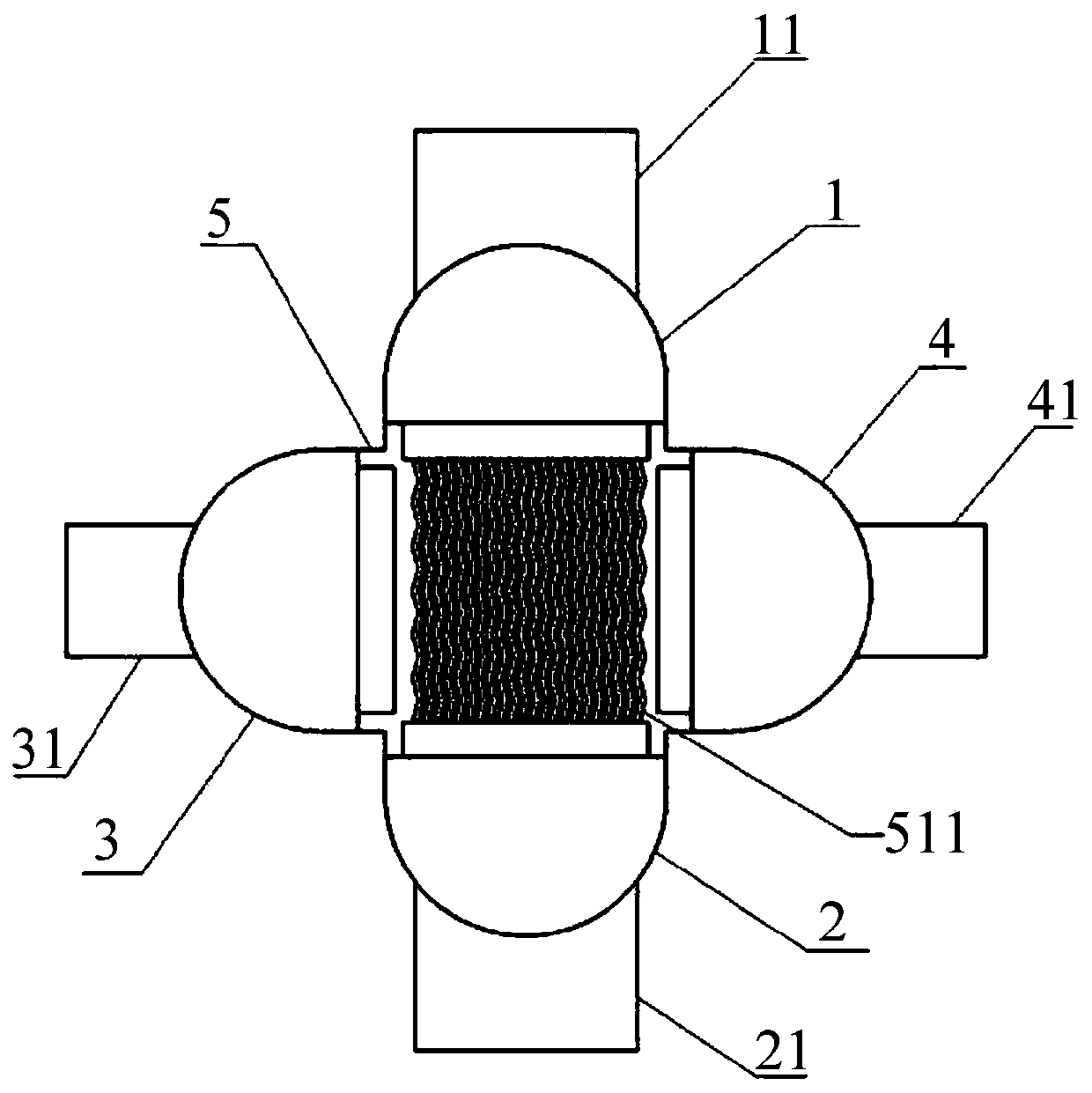
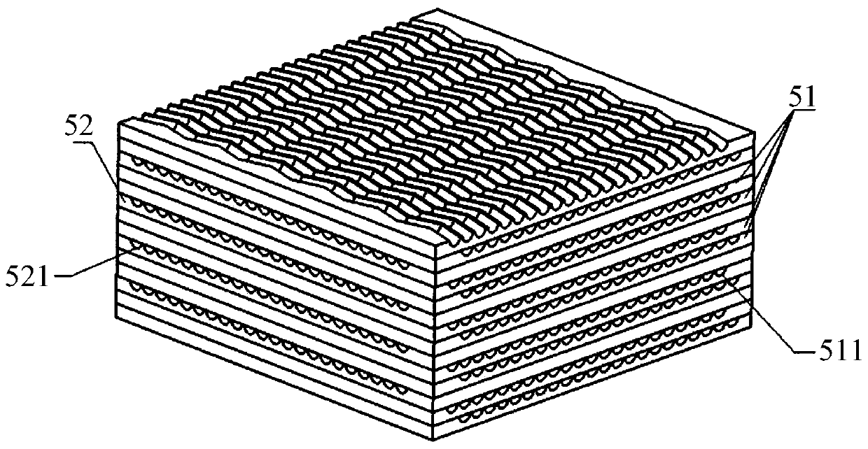
The invention provides a printed circuit board type fused salt heat exchanger adopting double-layer board arrangement. The printed circuit board type fused salt heat exchanger adopting double-layer board arrangement comprises a shell and a heat change board core arranged in the shell. The heat exchange board core comprises at least one periodical structure. Each periodic structure is composed of a first cold salt heat exchange board, a second cold salt heat exchange board and a hot salt heat exchange board, wherein the first cold salt heat exchange board, the second cold salt heat exchange board and the hot salt heat exchange board are sequentially stacked. Each first cold salt heat exchange board and each second cold salt heat exchange board are provided with multiple cold salt flow channels, wherein the flowing directions of the multiple cold salt flow channels are parallel. Each cold salt flow channel extends from the longitudinal first end of the corresponding cold salt heat exchange board to the longitudinal second end of the corresponding cold salt heat exchange board. Each hot salt heat exchange board is provided with multiple hot salt flow channels. Each hot salt flow channel extends from the transverse first end to the transverse second end of the corresponding hot salt heat exchange board. By the adoption of the printed circuit board type fused salt heat exchanger adopting double-layer board arrangement, it is avoided that fused salt causes blockage of the flow channels in a low-temperature environment, it is also avoided that in a high-temperature environment, the fused salt causes a thermal expansion effect on the flow channels of the heat exchanger, and the service life of heat exchange equipment is prolonged.

Description

technical field [0001] The invention relates to the field of heat exchange devices, in particular to a printed circuit board type molten salt heat exchanger arranged with double-layer plates. Background technique [0002] Heat exchangers are widely used in petrochemical, aerospace, ocean engineering, shipbuilding, nuclear power and other industrial fields, which can realize heat exchange between different working fluids, but the existing types of heat exchangers generally have low heat transfer area density. , large volume and weight, poor high temperature and high pressure resistance, and low heat transfer efficiency, especially in the field of nuclear power. With the popularization and application of fourth-generation nuclear reactors, heat exchangers built by traditional welding methods cannot meet the requirements of high temperature and high pressure media in nuclear reactors. Requirements. New high-efficiency heat exchange equipment with high temperature and high pres...

Claims


Application Information

Patent Timeline
Patent Type & Authority Patents(China)
IPC IPC(8): F28D9/04F28F9/18
CPCF28D9/0037F28D9/04F28F9/18
Inventor 杜培君孔巧玲黄伟光
Owner SHANGHAI ADVANCED RES INST CHINESE ACADEMY OF SCI
Learn More