Inverter boost current-loop vector auxiliary control method

An auxiliary control and current loop technology, applied in the direction of converting AC power input to DC power output, electrical components, output power conversion devices, etc., can solve the problem of reducing system stability, increasing Boost inductance loss, and affecting the maximum power of the battery panel. Point tracking, etc.

Active Publication Date: 2017-06-27
ZHEJIANG EIFESUN ENERGY TECH
View PDF4 Cites 2 Cited by
  • Summary
  • Abstract
  • Description
  • Claims
  • Application Information

AI Technical Summary

Problems solved by technology

[0003] Since the average value of the bus voltage is constant for Boost, and the soft voltage characteristics of solar panels make it possible to control the battery input voltage simply by fixing the Boost duty cycle, but in single-phase grid-connected inverters There is a power pulsation with a larger amplitude twice the power on the middle bus. The control method with a fixed duty ratio is adopted. The higher the output power, the lower the bus capacitance, the smaller the Boost inductance, and the higher the oscillation amplitude of the Boost current. The higher the value, the higher the Boost indu

Method used


Image

  • Inverter boost current-loop vector auxiliary control method
  • Inverter boost current-loop vector auxiliary control method
  • Inverter boost current-loop vector auxiliary control method

Examples


Embodiment Construction

[0031] In order to make it easy to understand the technical means, creative features, goals and effects achieved by the present invention, the following examples are combined with the appended figure 1 to attach Figure 5 The technical solutions provided by the present invention are described in detail, but the following content is not intended as a limitation of the present invention.

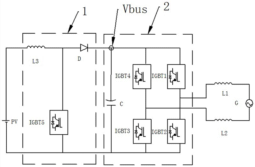
[0032] refer to figure 1 As shown, the structure of the existing photovoltaic grid-connected inverter is as follows, Vpv is defined as the Boost input voltage, Vbus is the Boost output voltage, Idc is the Boost current, L is the Boost inductance value, and Ton is the opening coefficient of BoostPwm. The value range is 0- 1. Define the Boost circuit to work in continuous current mode, and find the current increment in a single PWM cycle

[0033]

[0034] Simplifies to:

[0035]

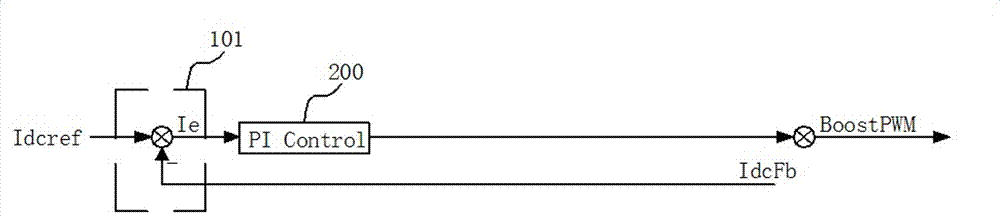
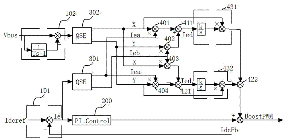
[0036] In the current loop control period, Vpv can be considered as a constant, then the control output of ...


PUM


Abstract

The present invention provides an inverter boost current-loop vector auxiliary control method. The method comprises the step of providing a first acquisition unit to acquire the deviation current in real time. The method further comprises an acquisition step: providing a second acquisition unit to acquire bus ripples in real time; a decomposition step: providing a first orthogonal extractor to conduct the orthogonal decomposition of the deviation current so as to obtain a first real component and a first imaginary component; providing a second orthogonal extractor to conduct the orthogonal decomposition of the bus ripples so as to obtain a second real component and a second imaginary component; an operation step: providing a first vector-synthesis unit to generate a first control current; and a control step: providing an integral controller to respectively conduct the integration control for the first control current and a second control current so as to enable the first control current and second control current to be zero respectively. According to the technical scheme of the invention, bus ripples and acquiring error currents are acquired, and the closed loop control process is conducted simultaneously. In the case of frequency changes, the control method is more stable compared to a proportional resonance controller.

Description

technical field [0001] The invention relates to the technical field of photovoltaic inverter control, in particular to an inverter Boost current loop vector auxiliary control method. Background technique [0002] As the key equipment for photovoltaic power generation, distributed photovoltaic grid-connected inverters mostly adopt DC-DC boost and DC-AC inverter two-level grid-connected topology (boost side 1 and inverter side 2). figure 1 As shown, the inverter side 2 controls the grid-connected current and the DC bus voltage, and the boost side 1 controls the input current and voltage of the battery panel to complete the tracking of the maximum power point; [0003] Since the average bus voltage is constant for Boost, and the soft voltage characteristics of solar panels make it possible to control the battery input voltage simply by fixing the Boost duty cycle, but in single-phase grid-connected inverters There is a power pulsation with a larger amplitude twice the power on...

Claims


Application Information

Patent Timeline
IPC IPC(8): H02M7/5387
CPCH02M7/5387H02M1/007
Inventor 李彬彬胡浙东李赟
Owner ZHEJIANG EIFESUN ENERGY TECH
Why Eureka
Try Eureka