Exhaust gas denitration device and method of controlling exhaust gas denitration device

A waste gas and denitrification technology, which is applied in the direction of electric control of exhaust treatment devices, exhaust devices, chemical instruments and methods, etc., can solve problems such as high cost of combustion-supporting burners, changes in flow and temperature, and complicated device structures

Active Publication Date: 2018-11-23
MITSUBISHI HEAVY IND LTD +2
View PDF8 Cites 0 Cited by
  • Summary
  • Abstract
  • Description
  • Claims
  • Application Information

AI Technical Summary

Problems solved by technology

[0009] However, the exhaust gas denitrification device for ships in Patent Document 1 uses a dedicated combustion-supporting burner to heat the engine exhaust gas, and there are problems such as the installation of the combustion-supporting burner and the high cost of fuel.
[0010] In addition, the low-temperature denitrification device of Patent Document 2 introduces the engine exhaust gas discharged from the diesel engine for power generation installed separately from the diesel engine into the exhaust flow path, but the flow rate of the engine exhaust gas discha

Method used


Image

  • Exhaust gas denitration device and method of controlling exhaust gas denitration device
  • Exhaust gas denitration device and method of controlling exhaust gas denitration device
  • Exhaust gas denitration device and method of controlling exhaust gas denitration device

Examples


Embodiment Construction

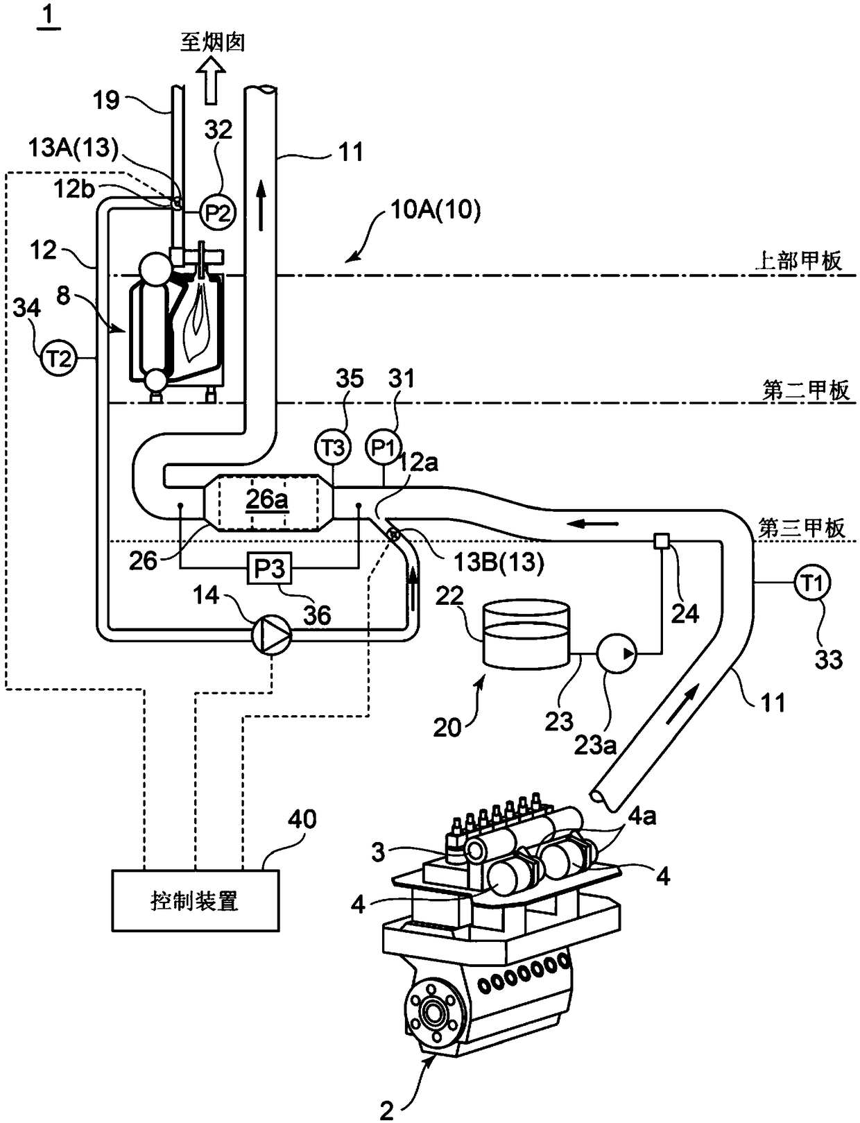
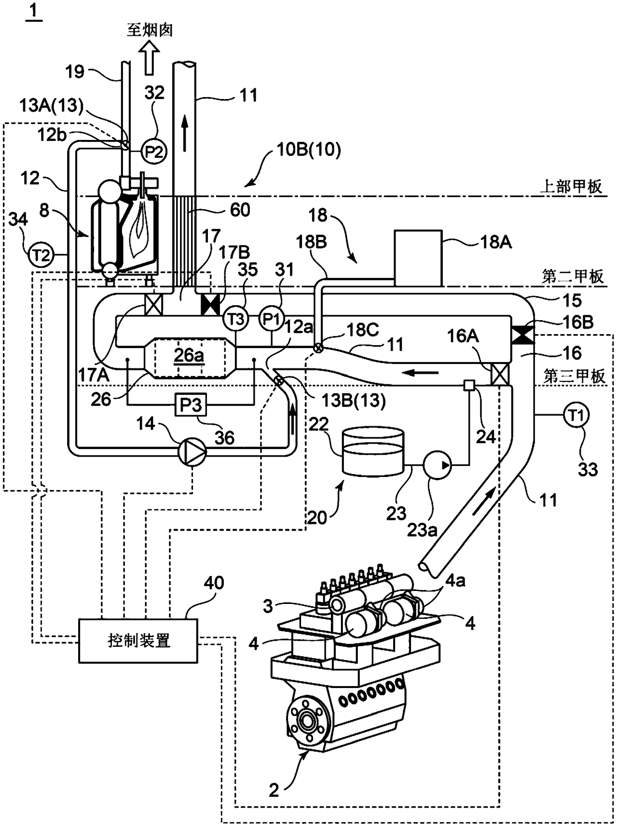
[0073] Hereinafter, several embodiments of the present invention will be described with reference to the drawings. However, dimensions, materials, shapes, relative arrangements, etc. of components described as embodiments or shown in the drawings are not intended to limit the scope of the present invention, but are merely illustrative examples.

[0074] For example, expressions such as "in a certain direction", "along a certain direction", "parallel", "orthogonal", "center", "concentric" or "coaxial" indicating relative or absolute configurations are not only strictly It shows such an arrangement, and also shows a state of being relatively displaced by an angle or a distance to the extent that a tolerance or the same function can be obtained.

[0075] For example, expressions such as "same", "equal" and "homogeneous" indicating that things are in an equal state not only strictly represent an equal state, but also express a state where there is a difference in the degree of tol...


PUM


Abstract

An exhaust gas denitration device for reduction of nitrogen oxides contained in engine exhaust gas discharged from a main engine mounted on a ship, the exhaust gas denitration device being provided with: an exhaust flow passage through which the engine exhaust gas discharged from the main engine flows; a reducing agent storage tank; a reducing agent spray nozzle; a denitration reactor including adenitration catalyst; a boiler exhaust gas conduit which guides boiler exhaust gas discharged from a boiler mounted on the ship to the upstream side of the denitration reactor in the exhaust flow passage; a boiler exhaust gas control valve which controls the flow of boiler exhaust gas in the boiler exhaust gas conduit; and a blower which blows the boiler exhaust gas flowing through the boiler exhaust gas conduit to the downstream side.

Description

technical field [0001] The invention relates to a waste gas denitrification device and a control method for the waste gas denitrification device. Background technique [0002] Affected by the tightening of environmental regulations in recent years, the reduction of nitrogen oxides (NOx) contained in the exhaust gas from the engine is also required in the marine two-stroke diesel engine used as the main engine of the ship. As a method for reducing NOx contained in engine exhaust gas, for example, a selective catalyst reduction method (SCR method) is conventionally known in which a reducing agent is injected into engine exhaust gas to reduce nitrogen oxide (NOx) to Nitrogen (N 2 ) and water (H 2 O). [0003] SCR catalysts that are generally distributed are premised on continuous use and use at an activation temperature (for example, 300° C. or higher). However, due to the low temperature of the engine exhaust gas discharged from the above-mentioned two-stroke diesel engine ...

Claims


Application Information

Patent Timeline
IPC IPC(8): F01N3/08B01D53/94F01N3/20
CPCB01D53/94F01N3/08F01N3/20Y02T10/40B01D53/9413F01N3/0842F01N3/2066F01N3/2093F01N9/002F01N2610/1453F01N2900/1404
Inventor 中川贵裕平冈直大藤田胜也土屋聪志
Owner MITSUBISHI HEAVY IND LTD
Why Eureka
Try Eureka