Method for controlling an electric motor

A technology on the electric motor and the motor side, which is applied to the reluctance motor system and the field of reluctance motors, can solve problems such as insufficient speed adjustment and instability, and achieve the effects of simple control, reduced computing power, and reliable control methods

Active Publication Date: 2020-03-24
VOLKSWAGEN AG
View PDF7 Cites 0 Cited by
  • Summary
  • Abstract
  • Description
  • Claims
  • Application Information

AI Technical Summary

Problems solved by technology

Such a regulation of the intermediate circuit voltage can however become unstable in the event of a change in the regulation stage (Regelstrecke) parameter
Conservative design of the regulator can have insufficient regulation speed

Method used


Image

  • Method for controlling an electric motor

Examples


Embodiment Construction

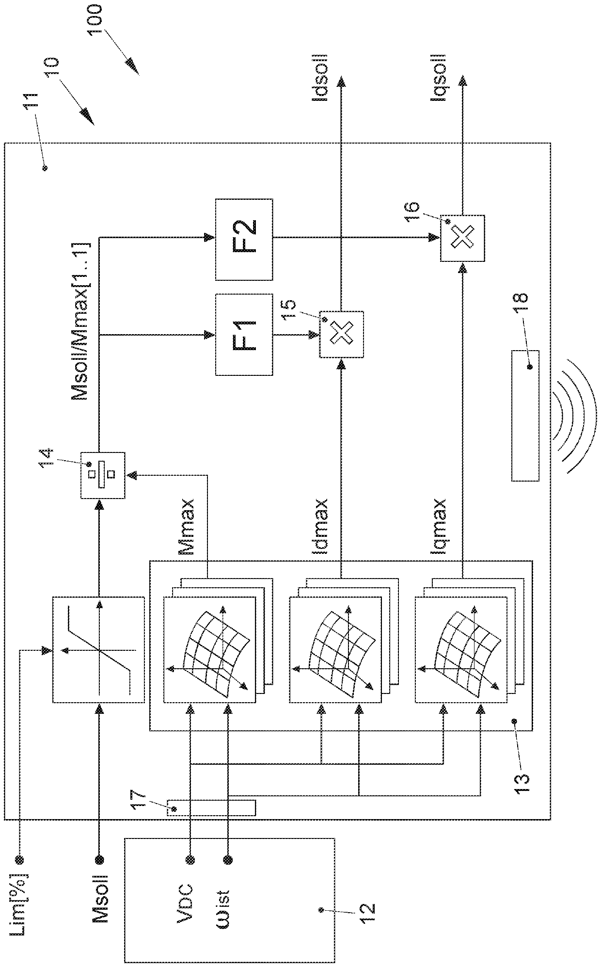
[0060] figure 1 A system 100 is shown for controlling an electric motor 10 , which can be designed in particular in the form of a reluctance motor. The system 100 is used to provide a desired torque Msoll of the electric motor 10 , which is produced by two setpoint current values ​​Idsoll, Iqsoll in the field coordinates d, q. For this purpose, according to the invention it is provided that the setpoint current values ​​Idsoll, Iqsoll are passed through the motor-side control unit 11 by means of the operating point-dependent characteristic field Mmax (V DC ,ω ist ), Idmax(V DC ,ω ist ), Iqmax(V DC ,ω ist ) to be determined according to the applied intermediate circuit voltage V of the electric motor 10 DC and / or speed ω ist The maximum torque Mmax of the electric motor 10 and / or the two corresponding current values ​​Idmax, Iqmax are plotted.

[0061] In order to generate a desired torque Msoll or setpoint torque of electric motor 10 , two setpoint current values ​​Ids...


PUM


Abstract

The invention relates to a method for controlling an electric motor (10), in particular a reluctance motor, in order to provide a desired torque (Msoll) of the electric motor (10) which is generated by two current setpoints (Idsoll, Iqsoll) in field coordinates (d, q). For this purpose, it is provided according to the invention that the current setpoints (Idsoll, Iqsoll) are determined by a motor-side control unit (11) with the aid of operating point-dependent maps (Mmax (VDC, omegaactual), Idmax (VDC, omegaactual), Iqmax (VDC, omegaactual)) which represent a maximum torque (Mmax) of the electric motor (10) and/or two corresponding current values (Idmax, Iqmax) depending on an applied intermediate circuit voltage (VDC) and / or a speed (omegaactual) of the electric motor (10).

Description

technical field [0001] The invention contemplates a method for controlling an electric motor, in particular a reluctance motor, according to the preamble of the independent method claim. Furthermore, the invention relates to an electric motor according to the preamble of the independent device claim. Furthermore, the invention relates to a system for controlling an electric motor, in particular a reluctance motor, according to the preamble of the independent system claim. Background technique [0002] In the drive of electric vehicles, synchronous machines excited by permanent magnets are mostly used as electric motors. A disadvantage of permanent magnet excited synchronous machines is the higher cost due to the use of rare earths. Using a reluctance motor as an electric motor is an alternative to reduce costs. In order to make optimal use of the intermediate circuit voltage, regulation of electric motors is frequently used, which uses the D component of the current as th...

Claims


Application Information

Patent Timeline
Patent Type & Authority Applications(China)
IPC IPC(8): H02P21/00H02P25/08
CPCH02P21/00H02P25/08H02P21/0025H02P21/0014H02P21/20H02P29/60
Inventor U.哈尔曼V.布拉克霍夫
Owner VOLKSWAGEN AG
Why Eureka
Try Eureka