Super-large diameter shield cutterhead system used in hard-soft heterogeneous ground

A technology with super large diameter and uneven hardness, which is applied in mining equipment, earthwork drilling, tunnels, etc. It can solve the difficulties of large-diameter main bearing processing and manufacturing, poor working stability of the shield machine, and uneven force on the cutterhead, etc. problems, to achieve the effects of excavation in grades of rock and soil, increasing the free surface of rock and soil, and saving costs

Pending Publication Date: 2017-06-30
CHINA RAILWAY TUNNEL GROUP CO LTD +1
12 Cites 22 Cited by

AI-Extracted Technical Summary

Problems solved by technology

[0005] In order to overcome the phenomenon of “unbalanced load” caused by the uneven force on the cutter head in the super-large diameter shield in the soft and hard stratum in the above-mentioned prior art, the poor working stability of the shield machine and the difficulty in manufacturing the large-diameter ma...

Method used

Described each order stirring bar stirs the crushed soil that enters soil bin by cutter head opening, makes to add plastic fluidization modification material and the dregs in soil bin fully contact, more effectively improves cutting soil in soil bin The plastic fluidity of the body can not only realize the balance of water and soil pressure, but also ensure smooth soil discharge. The screw conveyors of each stage make the soil body form a sealed soil plug during the process of discharging the soil from the inside to the outside, so as to maintain the stability of the pressure in the storage bin, and adjust the speed of the conveyor to control the pressure in the storage bin to achieve a dynamic balance of soil pressure.
The present invention has following advantages: 1, the shield cutterhead system of the present invention is used for the ultra-large diameter of hard and soft stratum, is the spatial interlaced structure by a plurality of cutterheads, effectively solves the problem of integral large-diameter cutterhead opening When digging soft and hard stratum, the uneven force will lead to the phenomenon of "unbalanced load" of the cutter head and the poor stability of the whole machine. Multi-layer cutter heads are jointly advanced to effectively improve the working environment of the cutter head and improve the performance of super large diameter shield machines. Adaptability and stability in soft and hard uneve...

Abstract

The invention discloses a super-large diameter shield cutterhead system used in a hard-soft heterogeneous ground. The super-large diameter shield cutterhead system comprises large-size cutterheads, a medium-size cutterhead, small-size cutterheads, spokes, a panel, a hob, a cutting knife, a leading knife, a center knife, a stirring rod, a reducer, a hydraulic motor, a power transmitting device, a shield and a spiral unearthing device; the front end cutterhead of the shield is nine cutterheads which are formed and arranged in a spatial crossing structure, and is divided into four-order cutterheads including the large-size cutterheads, the medium-size cutterhead, and the small-size cutterheads; the four-order cutterheads comprises a first-order cutterhead, second-order cutterheads, third-order cutterheads, and fourth-order cutterheads. According to the super-large diameter shield cutterhead system used in the hard-soft heterogeneous ground, multiple layers of cutterheads are distributed in a spatial crossing mode, each cutterhead can achieve individual control, and thus the excavation efficiency, precision and stability of the super-large diameter shield in construction of the hard-soft heterogeneous ground are improved. The use of a large diameter mainshaft bearing is prevented, and the manufacturing difficulty and transportation cost are lowered; through the adoption of the multiple layers of the cutterheads, loads of each part are lowered, and the service life of relevant parts of the cutterheads is prolonged.

Application Domain

Technology Topic

Image

  • Super-large diameter shield cutterhead system used in hard-soft heterogeneous ground
  • Super-large diameter shield cutterhead system used in hard-soft heterogeneous ground
  • Super-large diameter shield cutterhead system used in hard-soft heterogeneous ground

Examples

  • Experimental program(1)

Example Embodiment

[0022] Below in conjunction with accompanying drawing, the present invention is further described:
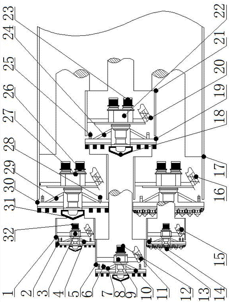
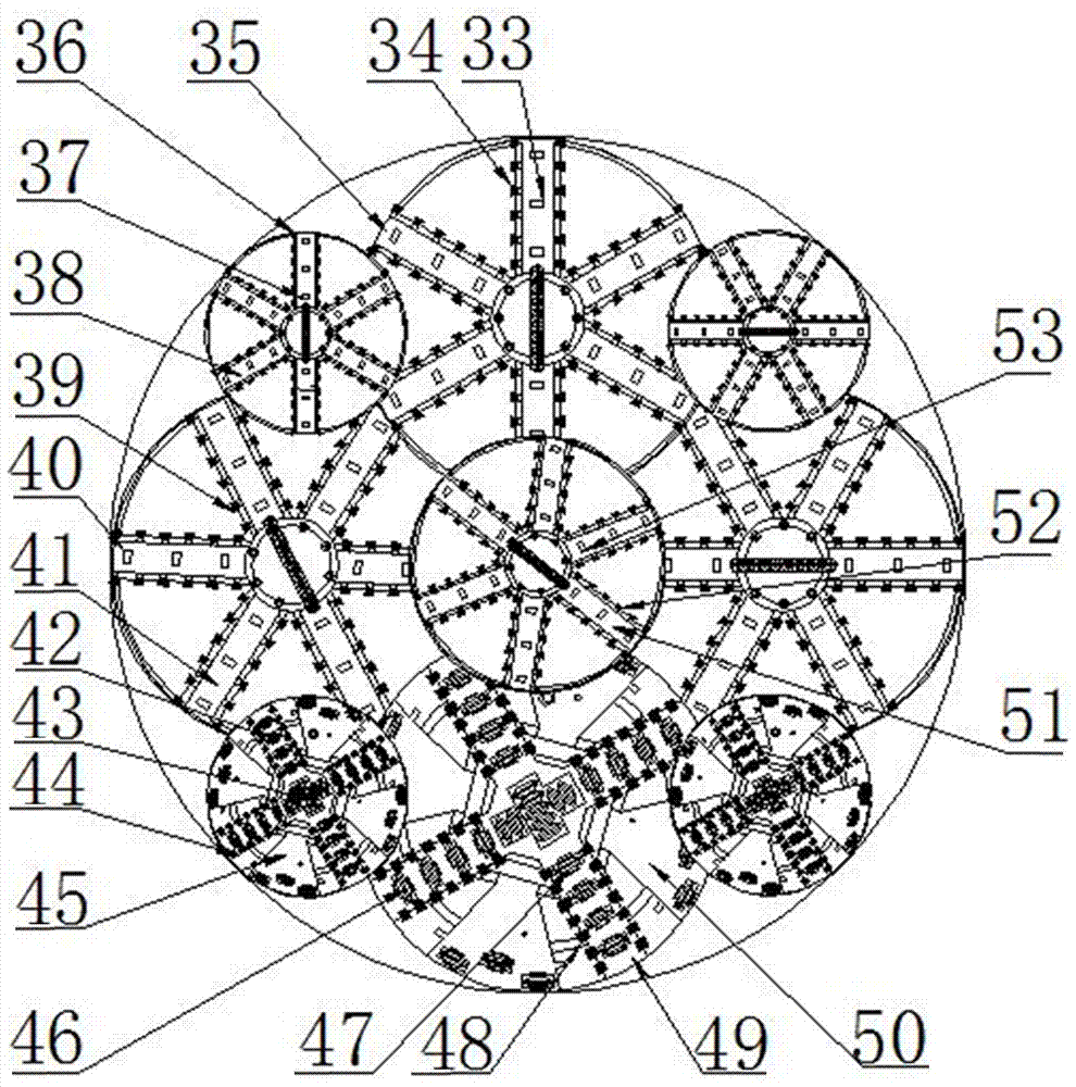
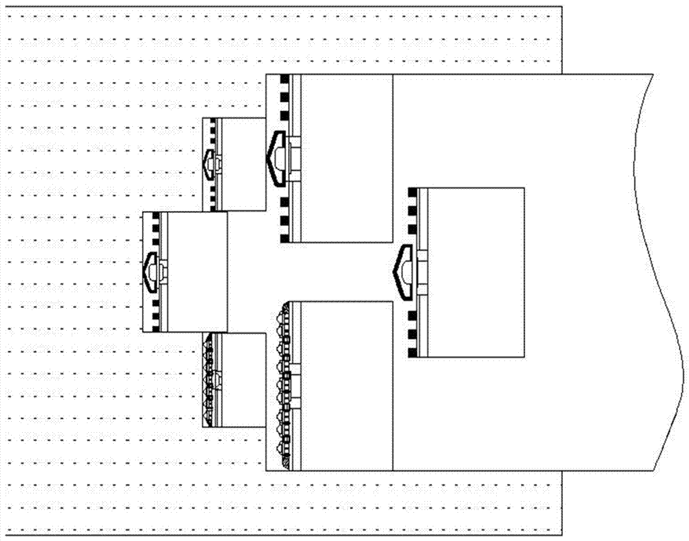
[0023] like figure 1 , figure 2 As shown, a shield cutter head system for super-large diameter of soft and hard uneven formation includes large cutter head, medium cutter head, small cutter head, spokes, panels, hob, cutter, advance cutter, center cutter, stirring cutter Rods, reducers, hydraulic motors, power transmissions, shields, screw excavation devices. It is characterized in that the front-end cutter head structure of the shield consists of 9 cutter heads in a spatially staggered structure, including a large cutter head, a medium cutter head and a small cutter head. The first stage of the cutter head structure is a medium cutter head, and one medium cutter head is located in the center of the shield cutter head structure; the second stage of the cutter head structure is a small cutter head, with 4 small cutter heads, along the cutter head. The structure is evenly distributed in the circumferential direction; the third stage of the cutter head structure is a large cutter head, and 2 of the large cutter heads are installed symmetrically up and down the excavation axis; the fourth stage of the cutter head structure is a large cutter head, and the large cutter head is 2 Each is installed symmetrically on the left and right sides of the excavation axis. Nine different types of cutterheads have independent drive systems, which can be controlled individually.
[0024] The present invention adopts the combination form of four-stage cutter head, wherein the first-stage cutter head 10 adopts six spokes 51, and a first-stage advance knife 53 and a first-stage cutter 52 are installed on the spokes 51. The first-stage cutter head 10 The center position is equipped with a first-order fishtail knife 8, and a first-order hydraulic motor 12 is installed on the back of the end face of the first-order cutter head 10 as a power device for driving the cutter head to rotate. The output shaft of the first-order reducer 9 is connected with the first-order power transmission device 7, and the first-order power transmission device 7 is fixedly connected with the cutter head. The back end face of the first-order cutter head 10 is provided with a first-order stirring rod 6 parallel to the axis of the cutter head, and a muck conveying device is arranged in the cutter head cavity, and the muck conveying device is a first-stage screw conveyor 11 .
[0025] There are two types of the second-stage cutter head, including the first spoke cutter head 2 located at the upper part of the whole cutter head system and the second panel type cutter head 13 at the lower part. The spoke-type cutter head 2 adopts 6 spokes 38, and a second-order advance knife 37 and a second-order cutter 36 are installed on the spokes 38, and a second-order fishtail knife 54 is installed in the center position, and the second-order advance knife 54 is installed on the spokes 38. The knife 37 is fixedly connected to the spokes 38 by welding. The panel-type cutter head 13 adopts four cutter beams 43 , and a second-order hob 42 and a second-order cutter 44 are installed on the cutter beams 43 , and a second-order center hob 14 is installed in the center position. A second-order hydraulic motor 32 is installed on the back end face of the second-order cutter head as a power device for driving the cutter head to rotate. The shaft is connected to the second-order power transmission device 4, and the second-order power transmission device 4 is fixedly connected with the cutter head. A second-order stirring rod 13 parallel to the axis of the second-order cutter head is provided on the back end face of the second-order cutter head, and a muck conveying device is arranged in the cutter head cavity, and the muck conveying device is a second-stage screw conveyor 15 .
[0026]There are two types of the third and third-order cutter heads, including the second spoke cutter head 30 at the upper part of the whole cutter head system and the second panel cutter head 50 at the lower part. The spoke-type cutter head 30 adopts 6 spokes 35, and a third-order advance knife 33 and a third-order cutter 34 are installed on the spokes 35, and a third-order fishtail knife 31 is installed in the center position, and the third-order advance knife 33 The spokes 35 are fixedly connected by welding. The panel-type cutter head 50 adopts four cutter beams 49 , and a third-order hob 47 and a third-order cutter 48 are installed on the cutter beam 49 , and a center hob 501 is installed in the center position. A third-order hydraulic motor 26 is installed on the back end face of the third-order cutter head as a power device for driving the cutter head to rotate. The main shaft of this third-order hydraulic motor 26 is connected 27 to the third-order reducer through a coupling piece. The output of the third-order reducer 27 The shaft is connected to the third-order power transmission device 29, and the third-order power transmission device 29 is fixedly connected to the cutter head. The back end face of the third-order cutter head is provided with a third-order stirring rod 28 parallel to the axis of the cutter head, and a muck conveying device is arranged in the cutter head cavity, and the muck conveying device is a three-layer screw conveyor 16 .
[0027] The fourth-order cutter head adopts 6 spokes 41, and a fourth-order advance knife 40 and a fourth-order cutter 39 are installed on the spokes 41, and a fourth-order fishtail knife is installed in the center of the fourth-order cutter head. 18. A fourth-order hydraulic motor 23 is installed on the back end face of the fourth-order cutter head as a power device for driving the cutter head to rotate. The main shaft of this fourth-order hydraulic motor 23 is connected to the fourth-order reducer 22 through a coupling, and the fourth-order reducer 22 The output shaft is connected to the fourth-order power transmission device 24, and the fourth-order power transmission device 24 is fixedly connected with the cutter head. A fourth-stage stirring rod 25 parallel to the axis of the cutter head is provided on the back end face of the fourth-order cutter head, and a muck conveying device is arranged in the cutter head cavity, and the muck conveying device is a fourth-stage screw conveyor 20 .
[0028] The stirring rods of each stage stir the broken soil that enters the soil bin through the opening of the cutter head, so that the plastic fluidized modified material is fully contacted with the slag in the soil bin, and the plasticity of the cutting soil in the soil bin is more effectively improved. The fluidity can not only balance the water and soil pressure, but also ensure smooth soil drainage. The screw conveyors of various stages make the soil body form a sealed plug during the process of discharging from the inside to the outside, keep the pressure in the silo stable, and adjust the speed of the conveyor to control the pressure in the soil silo to achieve dynamic balance of soil pressure.
[0029] During the construction of the large-diameter shield cutter head system of the present invention, when the excavation section is a soft soil layer, such as image 3 As shown in the figure, under the protection of the shield, the cutterheads of each stage carry out soil excavation, slag discharge and transportation, and advance forward, and each cutterhead does not interfere with each other when working. When the excavation stratum is uneven in hardness and softness, such as Figure 4 As shown in the figure, especially when there are local boulders or bedrock uplifts, the panel-type cutterhead hob at the lower part of the cutterhead system can effectively break up the hard strata, and the cutterhead system only needs to change the height of the bedrock uplift. The tools of the cutter head within the range can achieve rapid rock breaking, which overcomes the problems of uneven force and poor propulsion stability of the large-diameter whole cutter head in uneven soft and hard formations, improves the construction accuracy and effectively improves the cutter head work. surroundings.
[0030] The present invention has the following advantages: 1. The shield cutter head system of the present invention is used for the super-large diameter of the soft and hard uneven stratum. The plurality of cutter heads are in a spatially staggered structure, which effectively solves the problem of the overall large-diameter cutter head excavation soft and hard. When the stratum is uneven, the uneven force will lead to the phenomenon of "eccentric load" of the cutter head and the problem of poor propulsion stability of the whole machine. Adaptability and stability of uneven stratum; 2. The shield cutter head system of the present invention for the super-large diameter of the soft and hard uneven stratum no longer uses the large-diameter main bearing, which reduces the processing and manufacturing difficulty of the main bearing. Transportation and maintenance costs; 3. Multiple cutter heads are jointly stressed, which reduces the load of each main shaft component and prolongs the service life of related components; 4. The shield cutter of the present invention is used for the super-large diameter of the soft and hard uneven formation Each cutter head is not in the same plane, and the whole is arranged in a stepped manner, which increases the rock and soil free surface, which is conducive to the grading of rock and soil excavation, reduces tool wear, and improves the excavation rate; 5. The utility model is used for soft For the shield cutter head with super large diameter in hard uneven stratum, each cutter head can be controlled independently, and the respective propulsion speed and pressure can be adjusted in real time according to the cutting stratum conditions of each cutter head, so as to ensure the overall synchronous advancement and improve the tunnel construction accuracy; 6. The present invention It is a shield cutter head with super large diameter used in uneven soft and hard strata. When encountering local boulders or bedrock uplifts during the excavation process, it is only necessary to replace the cutter head of the cutter head within the height range of the bedrock uplift to achieve rapid rock breaking. . Easy to operate and save cost.
[0031] The above embodiments are only used to illustrate the preferred embodiments of the present invention, but the present invention is not limited to the above embodiments, and any modifications made within the spirit and principles of the present invention within the scope of knowledge possessed by those of ordinary skill in the art , equivalent substitutions and improvements, etc., shall be regarded as the protection scope of this application.

PUM

no PUM

Description & Claims & Application Information

We can also present the details of the Description, Claims and Application information to help users get a comprehensive understanding of the technical details of the patent, such as background art, summary of invention, brief description of drawings, description of embodiments, and other original content. On the other hand, users can also determine the specific scope of protection of the technology through the list of claims; as well as understand the changes in the life cycle of the technology with the presentation of the patent timeline. Login to view more.

Similar technology patents

Automatic sludge conveying device for pressure filter

Owner:苏州南风优联环保工程有限公司

Coal-rock drift quick tunnelling method

ActiveCN101975066ASuppression of spontaneous angerImprove working environmentTunnelsDrill holeCoal
Owner:河南省煤层气开发利用有限公司

Classification and recommendation of technical efficacy words

  • Improve working environment
  • Improve stability and adaptability

Pig manure centralized treatment and resource utilization method

Owner:SHANGHAI RUIDAO ENERGY SAVING ENVIRONMENTAL PROTECTION SCI & TECH CO LTD

Buoyant device used for blowout preventer in deepwater drilling water

ActiveCN101109277AImprove stability and adaptabilitySize breakthroughSealing/packingPipingMarine engineering
Owner:CHINA NAT OFFSHORE OIL CORP +1

Parameter adjustment method of system for supplying and recovering two types of steam in iron and steel enterprise

InactiveCN108534128AImprove stability and adaptabilityIncreased steam recoverySuperheating controlManufacturing convertersTraffic volumeProcess engineering
Owner:HANDAN IRON & STEEL GROUP +1

Basic storage device for valve production line

PendingCN108163446AImprove stability and adaptabilityConveyorsControl devices for conveyorsEngineeringProduction line
Owner:WUXI E LINK TECH

'8'-shaped hole sealing device and method for gear pump test

ActiveCN110630741AImprove stability and adaptabilitySmall sealing areaEngine sealsMaterial strength using tensile/compressive forcesEngineeringAero engine
Owner:BEIJING HANGKE ENGINE CONTROL SYST SCI & TECH
Why Eureka
Try Eureka