
Automatic pipe pressure experiment device

A kind of experimental equipment and pipe technology, which is applied in the direction of applying stable tension/pressure to test the strength of materials, etc., which can solve the problems of manual installation of fixtures, inconvenience, and long experiment cycle

Inactive Publication Date: 2017-06-30
合海橡塑装备制造有限公司
View PDF6 Cites 4 Cited by
  • Summary
  • Abstract
  • Description
  • Claims
  • Application Information

AI Technical Summary

Problems solved by technology

[0002] At present, the pressure test equipment for plastic pipes on the market can only carry out pressure tests on pipes with an inner diameter ranging from 10 to 630 mm, and cannot complete the test on large pipes, especially those with an inner diameter of 800 to 1200 mm
Some pressure test equipment for large-scale pipes is only limited to the sealing fixtures at both ends of the pipes. The fixtures need to be installed manually, and the pipes with the sealing fixtures installed can be transferred to the thermal insulation water tank with the help of large-scale hoisting equipment. The entire operation process needs to be completed manually. labor intensive
In addition, due to the long experiment period, the utilization rate of hoisting equipment is low. If a large-scale hoisting equipment is installed, the equipment cost will be high. If a mobile crane is used, the experimental space requirement will be large, which will bring inconvenience to the entire experiment.

Method used


Image

  • Automatic pipe pressure experiment device
  • Automatic pipe pressure experiment device
  • Automatic pipe pressure experiment device

Examples


Embodiment Construction

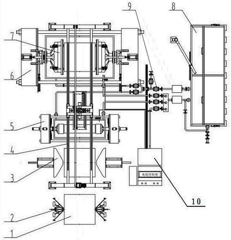
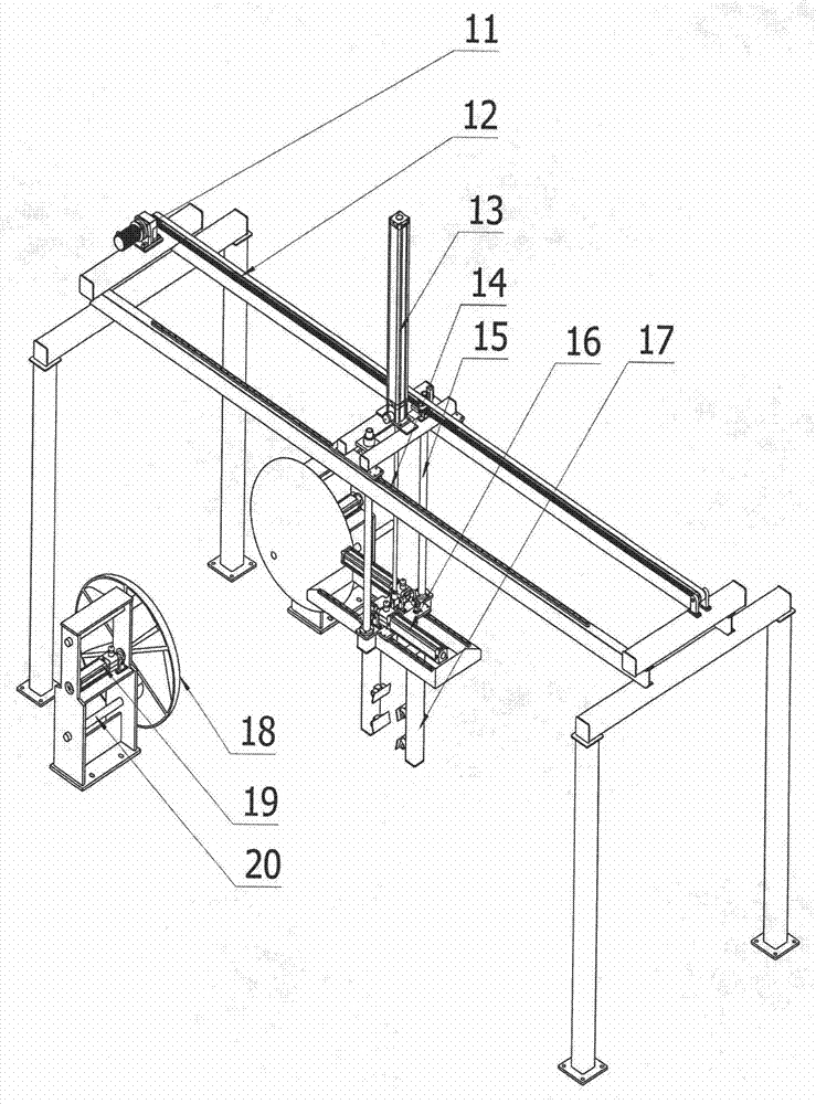
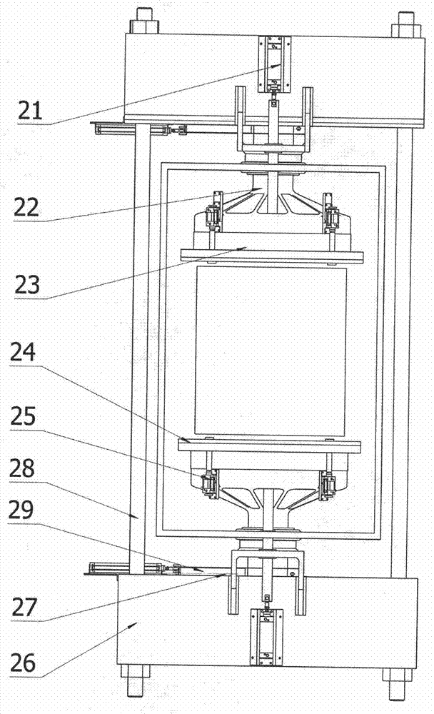
[0015] Such as figure 1 As shown, the automatic pipe pressure test device includes an inner wall support device 2, a centering device 3, a hoisting device 4, a small-size test box 5, a large-size test box 6, a sealing device 7, an insulated water storage tank 8, pipelines 9 and electrical appliances. 10 main components of the temperature control system. The inner wall supporting device 2 adopts a nut screw structure, one end of the screw is connected with the fixed plate of the long arm through a bearing, one end is connected with the hand wheel, one end of the short arm is hinged with the nut, and the other end is hinged with the long arm. The centering disc 18 in the centering device 3 is connected to the cylinder 19, one end of the guide rod 20 is connected to the centering disc 18 through a screw, and the other end passes through the support. In the hoisting device 4, the motor 11 is installed on the fixed crossbeam, and the moving crossbeam is driven to move by the belt ...


PUM


Abstract

The invention discloses an automatic pipe pressure experiment device. The automatic pipe pressure experiment device comprises an inner wall supporting apparatus, a centering apparatus, a hoisting apparatus, a small-specification experiment box, a large-specification experiment box, a sealing apparatus, an insulating water storage box, a pipeline, and an electrical and a temperature control system. A supporting range of the inner wall supporting apparatus is adjusted by adopting a nut and screw structure; the centering apparatus drives a conical centering disc by virtue of an air cylinder to position a pipe; the hoisting apparatus moves along a rectilinear guide rail by virtue of a motor and a belt, and a claw sheet is pushed by the air cylinder to grip different specifications of pipes; the large and the small test boxes push a pushing rod by virtue of the air cylinder so as to install and seal a clamp; and the air cylinder pushes an ejector plate, after the pipe is filled with high-pressure experiment water, the pushing rod tightly presses the ejector plate, and the pressure of the experiment water applied to the pushing rod is transferred to a stress support and a drawing rod, so that the stress support and the drawing rod are deformed to provide a thrust. By adopting the automatic pipe pressure experiment device, the automatic installation of large-sized pipe pressure experiments is realized, no large-sized hoisting device is needed, the labor intensity is reduced, and the cost and a needed space are saved.

Description

technical field [0001] The invention relates to an automatic pipe pressure test equipment Background technique [0002] At present, the pressure test equipment for plastic pipes on the market can only carry out pressure tests on pipes with an inner diameter ranging from 10 to 630 mm, and cannot complete the test on large pipes, especially those with an inner diameter of 800 to 1200 mm. Some pressure test equipment for large-scale pipes is only limited to the sealing fixtures at both ends of the pipes. The fixtures need to be installed manually, and the pipes with the sealing fixtures installed can be transferred to the thermal insulation water tank with the help of large-scale hoisting equipment. The entire operation process needs to be completed manually. Labor intensity is high. In addition, due to the long experiment period and the low utilization rate of hoisting equipment, if large-scale hoisting is installed, the cost of equipment will be high, and if a mobile crane i...

Claims


Application Information

Patent Timeline
IPC IPC(8): G01N3/12
CPCG01N3/12
Inventor 张道锋魏志军马明兴程春叶徐泓源张浩赵书孝
Owner 合海橡塑装备制造有限公司
Learn More