Electromagnetic-method-prospected primary-field loose-coupling reception device and method

A receiving device and electromagnetic method technology, applied in the field of electromagnetic method exploration, can solve problems such as strong mutual inductance, difficult resolution, and large changes in mutual inductance

Active Publication Date: 2017-06-30
CHONGQING CUILU DETECTION TECH CO LTD +1
View PDF6 Cites 13 Cited by
  • Summary
  • Abstract
  • Description
  • Claims
  • Application Information

AI Technical Summary

Problems solved by technology
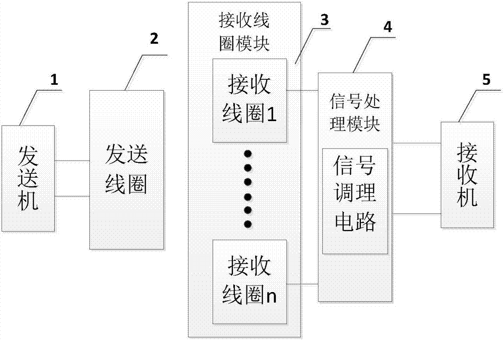
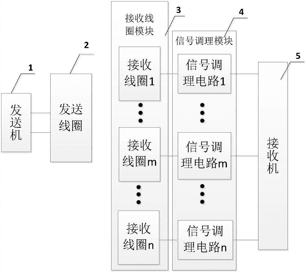
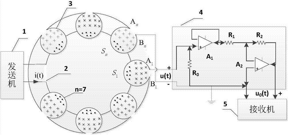
[0004] (1) There is a mutual inductance between the sending coil and the receiving coil. The signal induced by the receiving coil not only includes the secondary field signal collected by the receiver, but also aliases the excitation primary field generated by the electromagnetic transmitter. There are primary field and secondary field aliasing problem;
[0005] (2) Due to the large amplitude of the primary field signal and the small amplitude of the secondary field, it is very difficult to distinguish the secondary field from the background of the primary field, and the receiving signal has a large fluctuation range, making it difficult to receive the secondary field signal;
[0006] (3) The number of turns of the sending and receiving coils of the conventional small wire frame same point device is large, the mutual inductance influence is strong, the reliability of the conventional small wire frame same point device is poor, and it is difficult to be practically applied;
[0007] (4) Sending and receiving are two relatively independent systems. The relative position is uncertain during exploration, the mutual inductance changes greatly, and the distortion of the signal is ...

Method used


Image

  • Electromagnetic-method-prospected primary-field loose-coupling reception device and method
  • Electromagnetic-method-prospected primary-field loose-coupling reception device and method
  • Electromagnetic-method-prospected primary-field loose-coupling reception device and method

Examples


Embodiment 1

[0150] Embodiment 1, applied to the time-domain electromagnetic method, is carried out in the following order:

[0151] according to Figure 7 As shown, the central point O is selected on the plane, and the transmitting coil 2 is designed to be a 20-turn plane spiral coil, and each coil is approximately a circle; the radius of the innermost coil is 400mm, the radius of the outermost coil is 460mm, and the line width is 2.5mm. The distance between them is 0.5mm;

[0152] Design each sub-receiving coil as a 300-turn helical coil, and each turn of the coil is approximately a circle; the radius of the innermost coil is 100.5mm, the radius of the outermost coil is 120.5mm, the line width is 0.5mm, and the distance between lines is 0.5.

[0153] 2. Calculate the magnetic flux ψ passing through the sub-receiving coil m under the action of the primary field m1 (m=1, 2, 3, ... 7)

[0154]

[0155] Get: ψ m1 ≈1.5149×10 -9 i(t)(Wb)

[0156] 3. Start the transmitter, send as Fi...

Embodiment 2

[0164] Embodiment 2, applied to the frequency domain electromagnetic method, is carried out according to the following sequential steps;

[0165] 1, adopt the sending coil of embodiment 1 design, receiving coil group, get by the 2nd step of embodiment 1

[0166] ψ m1 ≈1.5149×10 -9 i(t) (Wb)

[0167] 2. Start the transmitter, send such as Figure 11 The sinusoidal current shown in the Figure 11 Middle: the horizontal axis is time t, each division is 0.02ms; the vertical axis is current, each division is 1A;

[0168] The signal is the sending current in Example 2. The frequency of the sending current is 10000 Hz. The sending current is measured by a current sensor. The conversion ratio of the current sensor is 100 mV / A, so the peak value of the sending current is 5.8 A. The sinusoidal current expression can be approximated: i(t)=5.5×cos(20000πt)(A);

[0169] 3. Calculate the primary field induced voltage of the inner receiving coil

[0170]

[0171] have to:

[0...

Embodiment 3

[0176] Embodiment 3, applied to the time-domain electromagnetic method, is carried out in the following order:

[0177] 1. Design of sending coil and receiving coil:

[0178] according to Figure 14 As shown, the central point O is selected on the plane, and the transmitting coil 2 is designed to be a 20-turn square solenoid; the side length of the square is 300mm, the line width is 2mm, and the distance between lines is 3mm;

[0179] The sub-receiving coil is designed as a 300-turn square solenoid; the side length of the square is 110mm, the line width is 2mm, and the distance between lines is 1.8mm;

[0180] 2. Calculate the magnetic flux ψ passing through the inner receiving coil 1 under the action of the primary field m1 :

[0181]

[0182] Get: ψ m1 ≈2.3149×10 -9 i(t) (Wb)

[0183] Among them: l 1 : The side length of each turn of the sub-receiving coil;

[0184] x: the x-coordinate of a point on the i-th coil plane of the sub-receiving coil;

[0185] y: the y...


PUM

PropertyMeasurementUnit
Radiusaaaaaaaaaa
Radiusaaaaaaaaaa
Line widthaaaaaaaaaa

Abstract

The invention discloses an electromagnetic-method-prospected primary-field loose-coupling reception device and a method, comprising: a transmitter, a transmission coil, a signal regulating module and a receiver. The two transmission output ends of the transmitter are connected with the two ends of the transmission coil. The device of the invention further comprises n reception coils that form a reception coil module in connection with the signal regulating module. The output end group of the signal regulating module is connected with the receiver. The reception coil module is arranged at the edge part of the transmission coil in such a manner that the two partially intersect, and some orthographic projection of the transmission coil overlaps some orthographic projection of the reception coils. According to the invention, the overlapping phenomenon of the primary field and the secondary field of reception coils is eliminated; the dynamic scope of the reception signal is reduced; the difficult problem with receiving weak secondary field signal is solved. In addition, the device and the method can be applied widely. As an integrated system, the device can be used and operated conveniently and the regulation effect is both precise and reliable.

Description

technical field [0001] The invention relates to the technical field of electromagnetic prospecting, in particular to a primary field weak coupling receiving device and method for electromagnetic prospecting. Background technique [0002] Electromagnetic exploration has been widely used in mineral exploration, engineering geological exploration, groundwater resources, underground pipelines and environmental geological exploration and other fields. Among them, frequency domain electromagnetic method and time domain electromagnetic method are commonly used. Electromagnetic transmitters are used to generate excitation primary fields. The secondary field induced by the geological body is collected by the receiver, and the structure of the geological body is detected by analyzing the secondary field. [0003] However, in the prior art, electromagnetic prospecting still has the following deficiencies: [0004] (1) There is a mutual inductance between the sending coil and the recei...

Claims


Application Information

Patent Timeline
IPC IPC(8): G01V3/10
CPCG01V3/104
Inventor 付志红王浩文李军强王耀陈景明朱学贵王唯邱婧竹魏秋生
Owner CHONGQING CUILU DETECTION TECH CO LTD
Why Eureka
Try Eureka