
Antenna device

An antenna device and antenna technology, which are applied in directions such as antennas, antenna supports/installation devices, and antenna components to achieve the effects of widening radiation bandwidth, increasing gain, and suppressing side lobes

Inactive Publication Date: 2017-07-04
AAC TECH PTE LTD
View PDF8 Cites 30 Cited by
  • Summary
  • Abstract
  • Description
  • Claims
  • Application Information

AI Technical Summary

Problems solved by technology

[0008] The purpose of the present invention is to provide an antenna device, which effectively solves the technical problem that the existing 5G high-frequency millimeter-wave antenna needs to separately open the antenna gap on the metal back shell

Method used


Image

  • Antenna device
  • Antenna device
  • Antenna device

Examples


Embodiment Construction

[0024] The following will clearly and completely describe the technical solutions in the embodiments of the present invention with reference to the accompanying drawings in the embodiments of the present invention. Obviously, the described embodiments are only some, not all, embodiments of the present invention. Based on the embodiments of the present invention, all other embodiments obtained by persons of ordinary skill in the art without making creative efforts belong to the protection scope of the present invention.

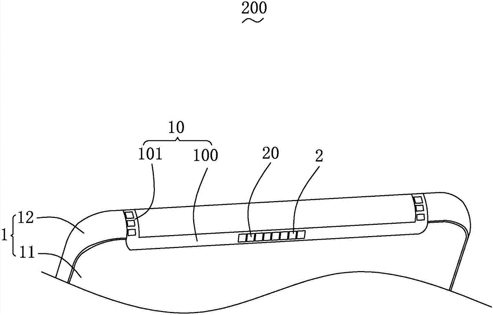
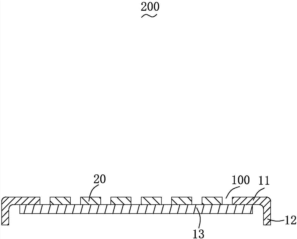
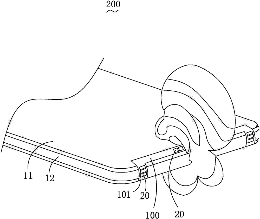
[0025] see figure 1 , figure 1 It is a structural schematic diagram of the antenna device of the present invention. The antenna device 200 includes a millimeter-wave microstrip antenna 2 assembled on the casing 1 of the electronic device, and the electronic device includes a main antenna (not shown) arranged in the casing 1, and the casing 1. It is preferably a metal shell, of course, it can also be made of other materials. The main antenna includes one or ...


PUM


Abstract

The invention provides an antenna device. The antenna device comprises a millimeter wave microstrip antenna, wherein the millimeter wave microstrip antenna is assembled on a shell of electronic equipment, the electronic equipment comprises a main antenna, the main antenna is arranged in the shell, an antenna gap is formed in the shell and is used for radiation / receiving of a radio frequency signal by the main antenna, the millimeter wave microstrip antenna comprises a plurality of unit antennas, the plurality of the unit antennas are arranged at intervals, and the plurality of the unit antennas and the shell are arranged at an interval and are arranged in the antenna gap in an array way. Compared with prior art, the antenna device provided by the invention has the advantages that the millimeter wave microstrip antenna is arranged in the antenna gap for radiation / receiving of the radio frequency by the main antenna, so that independent gap opening on the millimeter wave microstrip antenna is prevented, the same antenna clearance region can be shared with the main antenna, the design space of the millimeter wave microstrip antenna is saved, and the space utilization ratio is improved; and meanwhile, the radiation bandwidths of the unit antennas can also be effectively expanded, the gain is improved, the side lobe is suppressed, and the radiation efficiency of the antenna device is further improved.

Description

[0001] 【Technical field】 [0002] The present invention relates to the technical field of antennas, in particular to an antenna device. [0003] 【Background technique】 [0004] With the rapid development of mobile communication technology, the 5G era is coming. In 5G core technology, antennas are required to meet the design requirements of high frequency and MIMO multi-antenna arrays. [0005] Taking the mobile terminal mobile phone as an example, the current mainstream mobile phone adopts a metal back shell design. In order to realize the antenna design, it is necessary to open a slit on the all-metal back shell to realize the transmission and reception of signals by the antenna. However, when designing the 5G high-frequency millimeter-wave antenna, it is necessary to separately set the antenna gap on the metal back shell, which will inevitably result in an ugly appearance of the back shell of the mobile phone, which does not meet the aesthetic requirements of modern people, ...

Claims


Application Information

Patent Timeline
Patent Type & Authority Applications(China)
IPC IPC(8): H01Q1/24H01Q1/44
CPCH01Q1/242H01Q1/44
Inventor 路凯何伟苏蔚
Owner AAC TECH PTE LTD
Learn More