Charging circuit and charging method

A charging circuit and resistance technology, applied in battery circuit devices, secondary battery charging/discharging, circuit devices, etc., can solve the problems of low charging efficiency and large power loss.

Active Publication Date: 2020-08-04
SHANGHAI ZHONGKE SHENJIANG ELECTRIC VEHICLE
View PDF3 Cites 0 Cited by
  • Summary
  • Abstract
  • Description
  • Claims
  • Application Information

AI Technical Summary

Problems solved by technology

[0004] After verification, it is found that in the RC constant voltage charging mode, the charging efficiency will not exceed 50%, and it has nothing to do with the resistance blocking, the charging efficiency is low, and the power loss is large

Method used


Image

  • Charging circuit and charging method
  • Charging circuit and charging method
  • Charging circuit and charging method

Examples


Embodiment 1

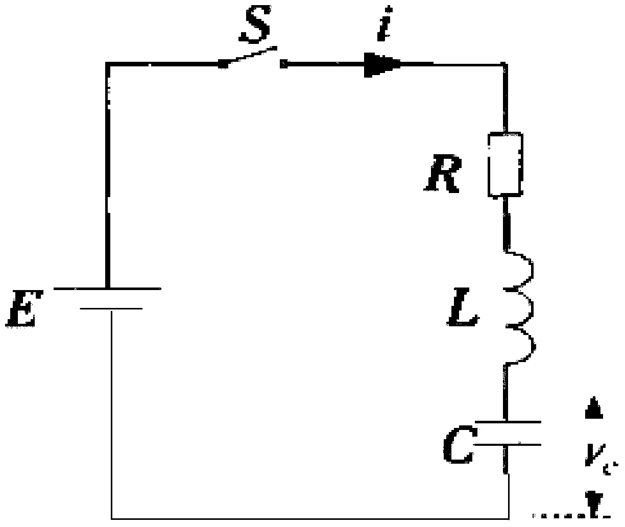
[0166]Embodiment 1: E=10V, R=2mΩ, L=2mH, C=500F, substitute the above specific values ​​into R 2 -4L / C=-4×10 -6 <0, formula (50) can be obtained according to formula (18), and formula (51) can be obtained according to formula (49):

[0167]

[0168]

[0169] According to the formula (50) and formula (51), the voltage and the voltage during the charging process are simulated to obtain Figure 4 , Figure 4 It is a simulation diagram of charging current and voltage in the charging method provided by an embodiment of the present invention. Wherein, the solid line curve (Ic) is the charging current curve, and the dotted line curve (Uc) is the charging voltage curve. It should be noted that, in order to display on the same coordinate axis, the ordinate of Ic is reduced by 100 times.

[0170] Ideally, that is, when R=0, According to formula (18), we can get:

[0171]

[0172] When R=0, Transform formula (37) to get:

[0173]

[0174] in,

Embodiment 2

[0175] Embodiment two: E=10V, L=2mH, C=500F.

[0176] Substituting the above specific values ​​into Formula (52) can be obtained according to formula (19), and formula (53) can be obtained according to formula (49):

[0177]

[0178]

[0179] According to the formula (52) and formula (53), the voltage and the voltage during the charging process are simulated to obtain Figure 5 , Figure 5 It is a simulation diagram of charging current and voltage in the charging method provided by another embodiment of the present invention. Wherein, the solid line curve (Ic) is the charging current curve, and the dotted line curve (Uc) is the charging voltage curve. It should be noted that, in order to display on the same coordinate axis, the ordinate of Ic is reduced by 100 times.

[0180] After the charging current and charging voltage in the charging method of the present invention are described in detail with specific numerical values, the charging efficiency of the charging m...


PUM


Abstract

The invention provides a charging circuit and a charging method. The charging circuit comprises a direct current constant voltage source, a first switching tube, a second resistor, an inductor, a current transformer, a voltage detection apparatus, a supercapacitor, a second switching tube and a controller, wherein the controller generates a first path of pulse to control the switch on or switch off of the first switching tube and generates a second path of pulse to control the switch on or switch off of the second switching tube, according to the charging current of the supercapacitor obtained by the current transformer and the voltage at the two ends of the supercapacitor obtained by the voltage detection apparatus. By adoption of the embodiment of the charging circuit, the supercapacitor is charged in an RLC constant-voltage charging mode; the first switching tube and the second switching tube are triggered by adopting complementary pulses to realize charging control on the supercapacitor; and the charging circuit shares two switching tubes, so that the number of adopted devices is small.

Description

technical field [0001] The invention relates to electric vehicle technology, in particular to a charging circuit and a charging method. Background technique [0002] With the deepening of the awareness of environmental protection, electric vehicles with the characteristics of zero emission, no pollution, and high energy utilization are more and more favored by consumers. As a new type of energy storage element, supercapacitors are increasingly used in electric vehicles. [0003] When the supercapacitor is charged, the electrode surface is in an ideal polarized state, and the charge will attract the opposite-sex ions in the surrounding electrolyte solution, making them on the electrode surface, forming an electric double layer, and forming an electric double layer capacitance. At present, the supercapacitor is charged in the RC constant voltage charging mode, and the charging efficiency in this mode is [0004] After verification, it is found that in the RC constant volta...

Claims


Application Information

Patent Timeline
Patent Type & Authority Patents(China)
IPC IPC(8): H02J7/34H01M10/44
CPCH02J7/345
Inventor 张陈斌肖欣孙江明林利徐冲李祖喜杨士保张兴旺杨钢
Owner SHANGHAI ZHONGKE SHENJIANG ELECTRIC VEHICLE
Why Eureka
Try Eureka